All posts by wgarrett

Soapbox or gravity racer

This was one of my quicker projects – I found out about the race, due to start at 1000 on 1st Jan, with only a month to go. And to complicate matters, that month included xmas.

The chassis was fully modelled in CAD (Fusion360) to check that the intended 25mm square, 2mm thick wall, box section aluminium was going to be sufficiently strong and stiff. Aluminium may seem a strange choice for a sport where extra weight is usually an advantage but there were two conflicting briefs – when not being used for the race, it was to be used by kids and so needed to be light enough for them to push about. I took the view that we could always add weight for the race.

Continue reading Soapbox or gravity racer

Learning to weld aluminium

I was lucky enough to use a friend’s TIG welding setup earlier in the year to make a frame from stainless steel box section. Since I mostly machine aluminium in my workshop, I decided it was time to learn to weld pieces toegther, not just turn them into swarf. Here is my first attempt on a piece of 2mm thick sheet:

  
It took a couple of runs to get the current set to something reasonable, the early runs being just to the left of the torch. The longer weld is actually joining two pieces of sheet together; the reflections exaggerate the ripples. While this top side looks ok (pretty good I’d like to think for a first attempt), the weld doesn’t penetrate right through for most of the length so a bit more heat is needed next time. There is also some contamination of the weld visible (black holes), probably from something on the edges of the sheets, which I didn’t brush clean. 

Slotting head tool holder

I’ve had the slotting head for the Aciera F3 for a few months but haven’t used it yet, mostly because I haven’t had any tooling or tool holders for it. Now I want to cut an internal key way to fix a wheel onto its shaft, so it was time to make some tooling. 

The slotting head has a 12mm hole for a tool holder but I didn’t have any 12mm diameter steel, so I started with a 16mm bar. The result is shown below. From left to right: parallel 12mm shank to fit in head; 16mm collar; top end of the 4mm slanting hole for the cutter, tapped for a 5mm grub screw so that the amount of protrusion of the cutter can be adjusted by pushing it out; head of 5mm grub screw for clamping the cutter (this does go below the surface when tight).

  
4mm diameter tool steel bar held in the holder, from which I shall grind or mill a cutter for a piece of 1/8″ square section key steel. 

 
It’s certainly not the neatest tooling I’ve ever made, not helped by the design of my dividing head (in which I’d planned to hold the piece on the mill while drilling the various holes) not allowing me to hold the piece in a collet, since the draw bar would foul the table [correction: I later discovered that the drawbar can be removed once the collet is secured, so I could have used the dividing head]. There was also insufficient clearance under the vertical head to allow me to use a chuck on the dividing head, so the piece was simply held in a vice and all angles set by eye. 


Rack and pinion steering

One of my first experiments with 3D printing was a steering rack, pinion and housing for a little project I’m working on. It came out very nicely, in terms of both finish and fit. 

Top view. The ID of the bearing is 12mm. 

   
Front view, with bolt holes through the housing clearly visible. The rack and pinion are module 3, which seemed about the right size. 

 
I left spaces into which ball bearings were pressed, one above the pinion on the outside of the housing and one under the pinion inside the housing. 

   
The key way in the pinion is just visible through the bearing in the photo below. 


And with a 12mm OD stainless tube turned lightly to fit:


I did a couple of experimental universal joints, printing the whole assembly as one, to work out the optimum gap between moving parts:

  
Before deciding that I actually wanted two universal joints, with an extending section between. A little more time on the CAD and here is the result installed:

  
The bracket being held in place by a clamp contains two sets of bearings and will be bolted to the stainless box section. This was my first bit of aluminium welding for real. 

A quick test of the steering revealed that the universal joints were not strong enough; I am now working on a new solution. 

Preparing pinion blanks

Steps to prepare a blank for cutting teeth using the Hauser 333. The blank must be 12mm long from the points of the male centres, with at least a 5mm length reduced below the root diameter in order to give cutter clearance. 

  1. Use 1/8″ O1 steel rod for pinions around 2mm diameter;
  2. Extend the rod about 15mm from the face of the collet;
  3. Using the left hand tool, cut a male centre on the end of the rod down to a fine point;
  4. Swap to the right hand tool and face the end, near the point, setting the collar to indicate zero;
  5. Rough turn down to approx 1.25mm diameter for a length of 5mm (this is needed for cutter clearance on the Hauser 333);
  6. Turn the roughed part down to the arbor diameter, probably 0.8mm, for a length of 5mm. This is one end complete;
  7. From the shoulder, rough turn a short length down to approx 2.1mm;
  8. From the shoulder, turn a 0.25mm length for the wheel rivet at 1.24mm diameter;
  9. From the shoulder, rough turn the blank to approx 2.1mm diameter for a total length of 12mm;
  10. From the shoulder, turn down to pinion full diameter (1.91mm for 12 leaf 0.14 module pinion) plus approx 0.03mm, for at least the length of the pinion teeth;
  11. Swap to the left hand tool and turn down the left hand arbor, cutting the pinion down to length;
  12. Swap to the right hand tool and use it to part off the blank, forming a male centre in the process. 

Pinion cutting on the Hauser 333

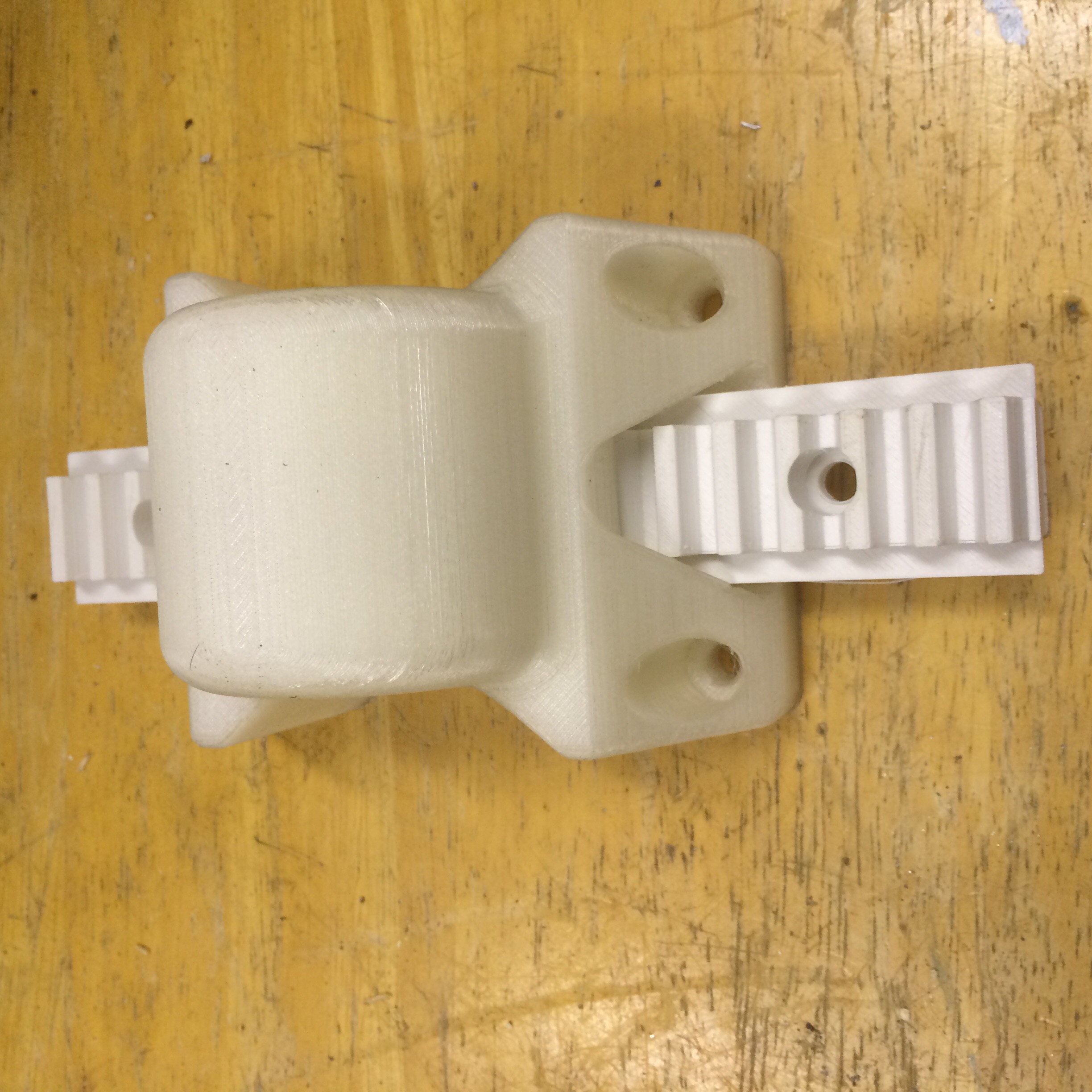
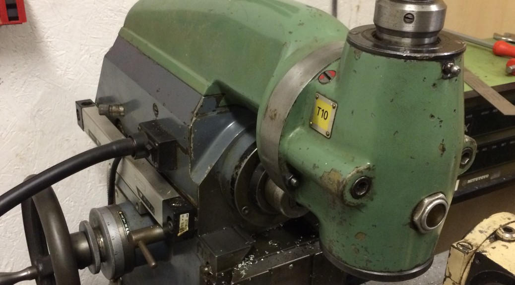
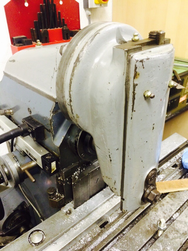
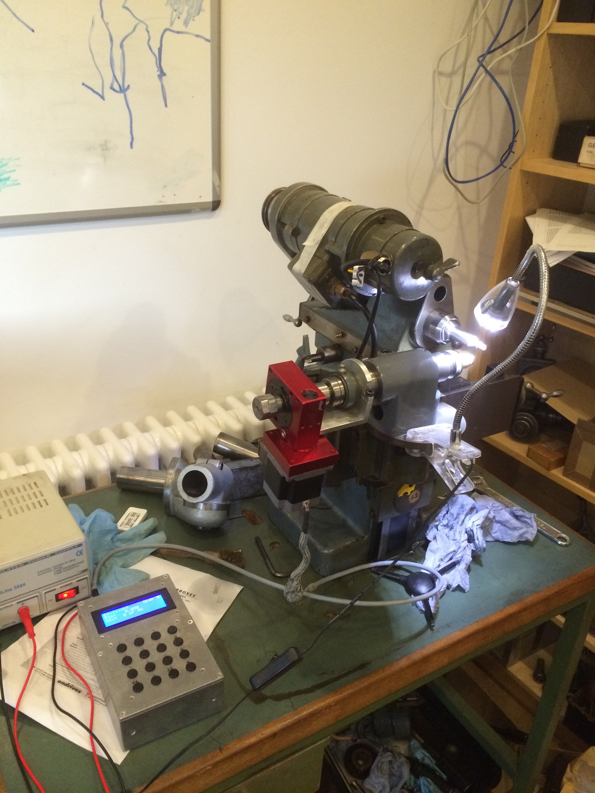
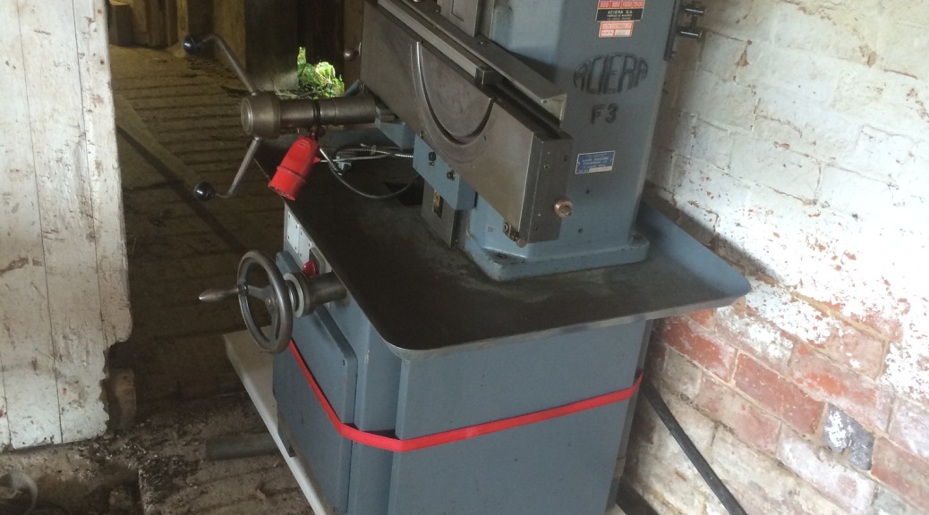
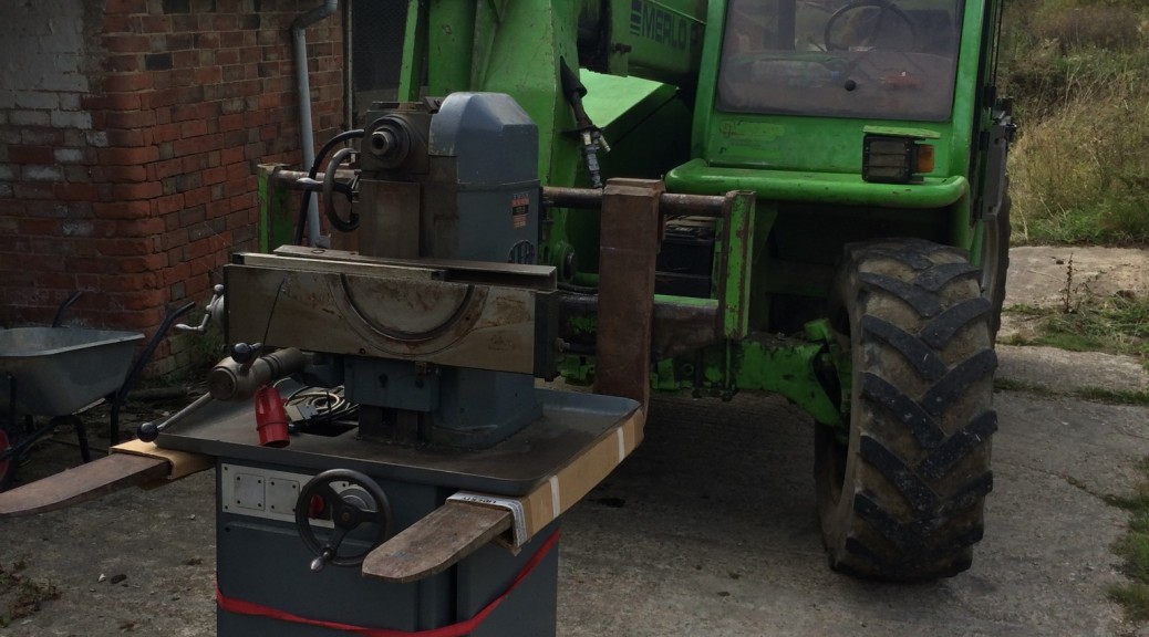
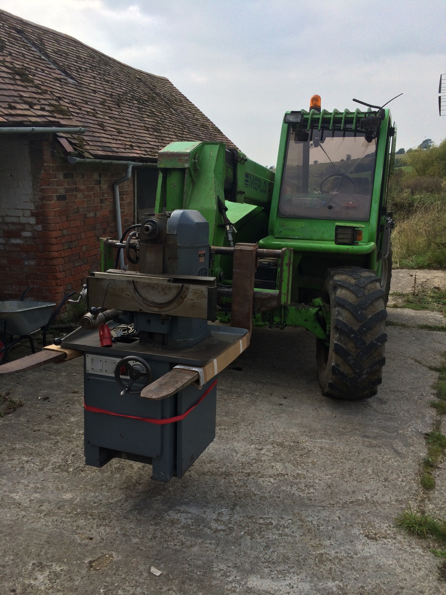
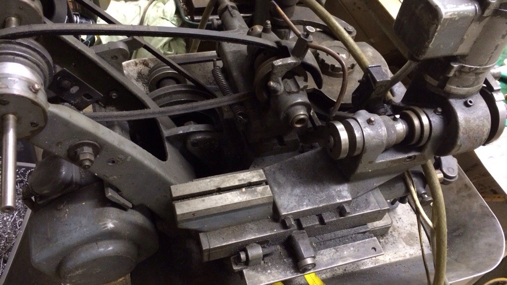
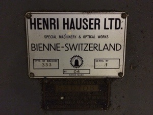
Having discovered that accurate centring of the cutter is critical when cutting pinions on the Aciera F1, I decided that it was time to set the Hauser 333 up as a dedicated pinion cutting machine. This would mean that the F1 was freed up for other jobs and that I would (hopefully) not have to go through the long process of centring a pinion cutter again. 

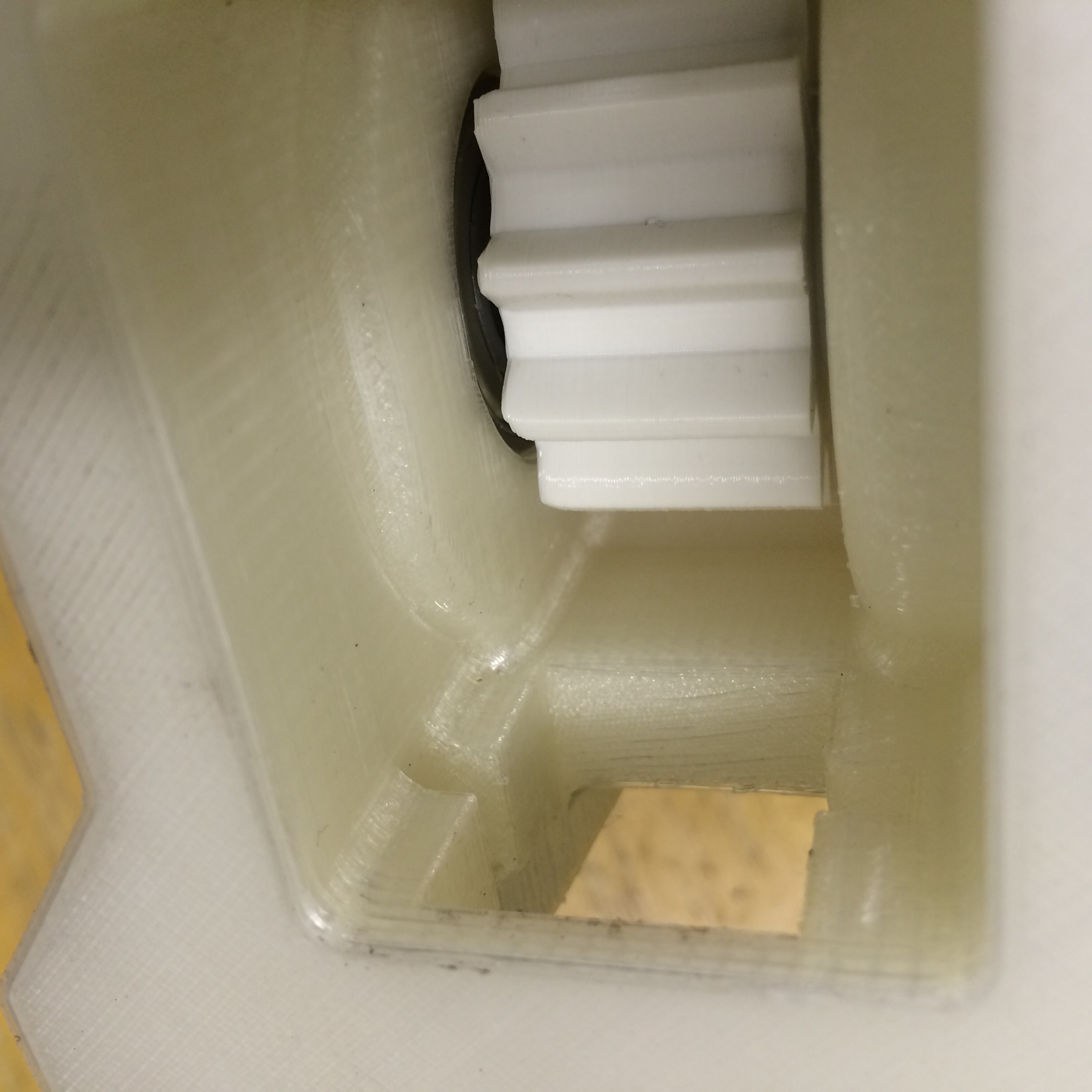
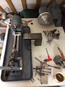
The Hauser has power feed in 4 separate axes but for this first test I did not want it to move in Z (depth of cut) or Y (cutter centring). The belt driving the cams was turned by hand to get the axes at the extremes of travel. 

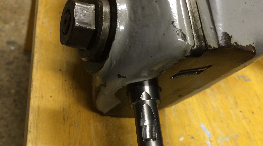
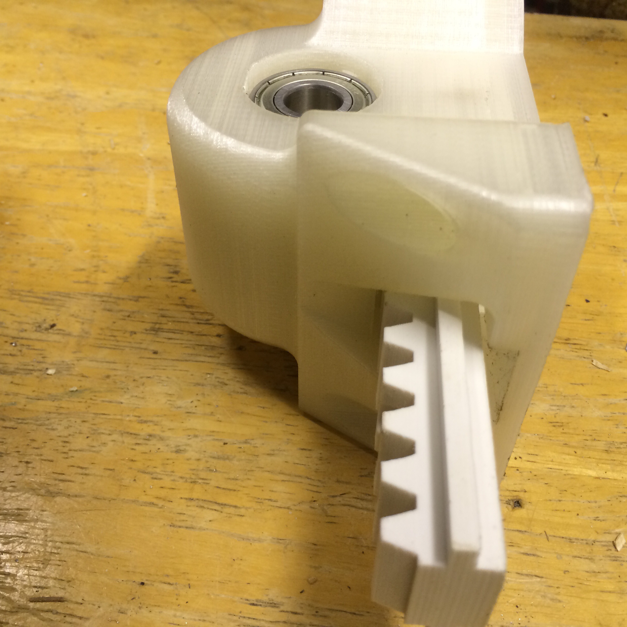
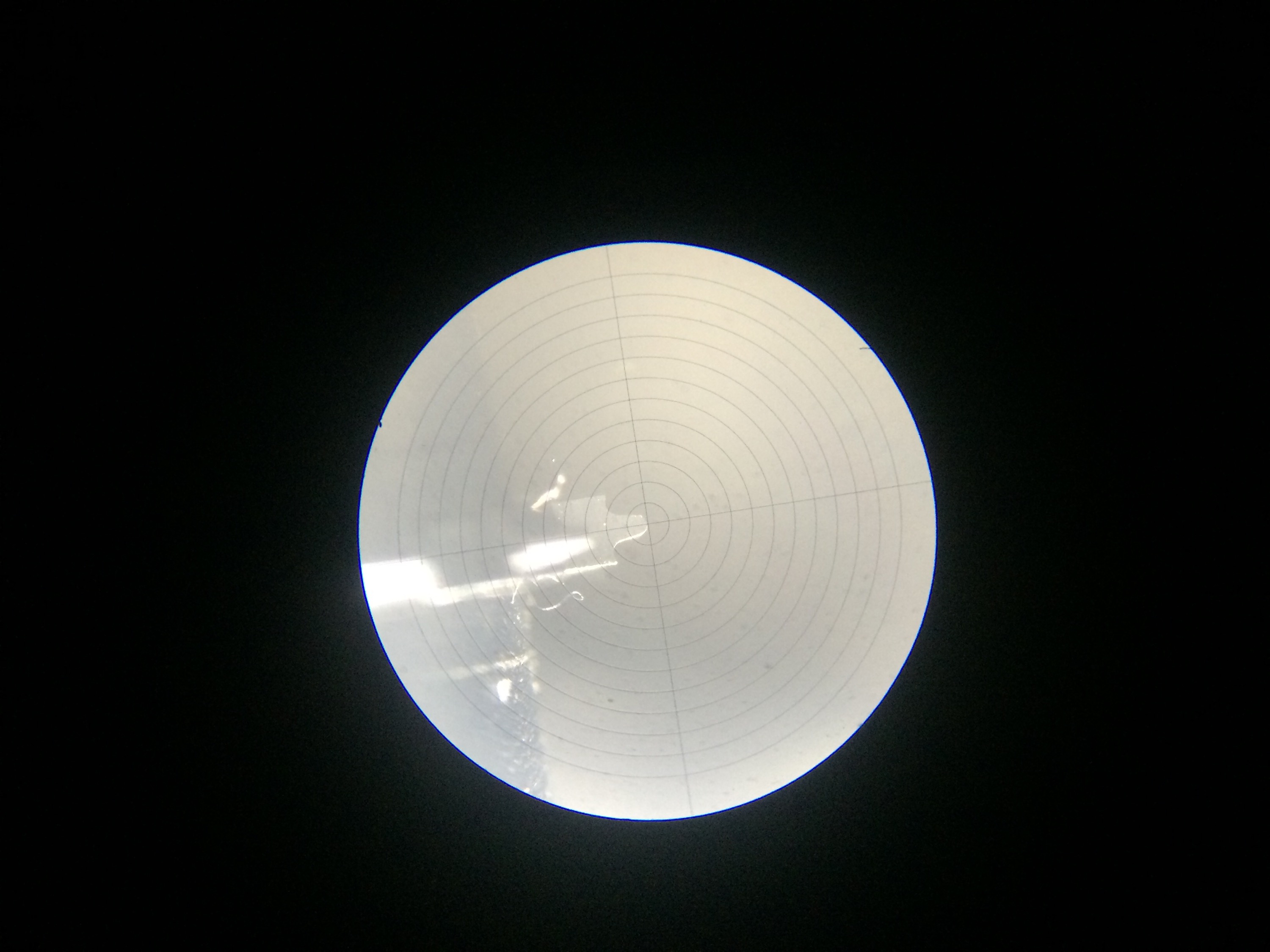
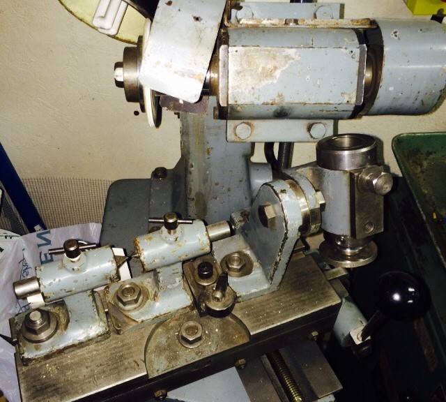
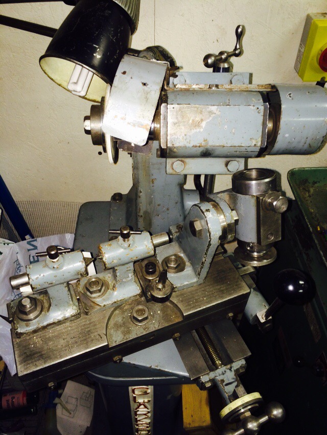
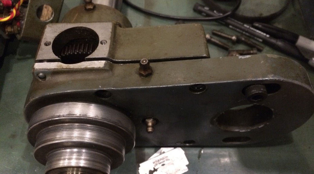
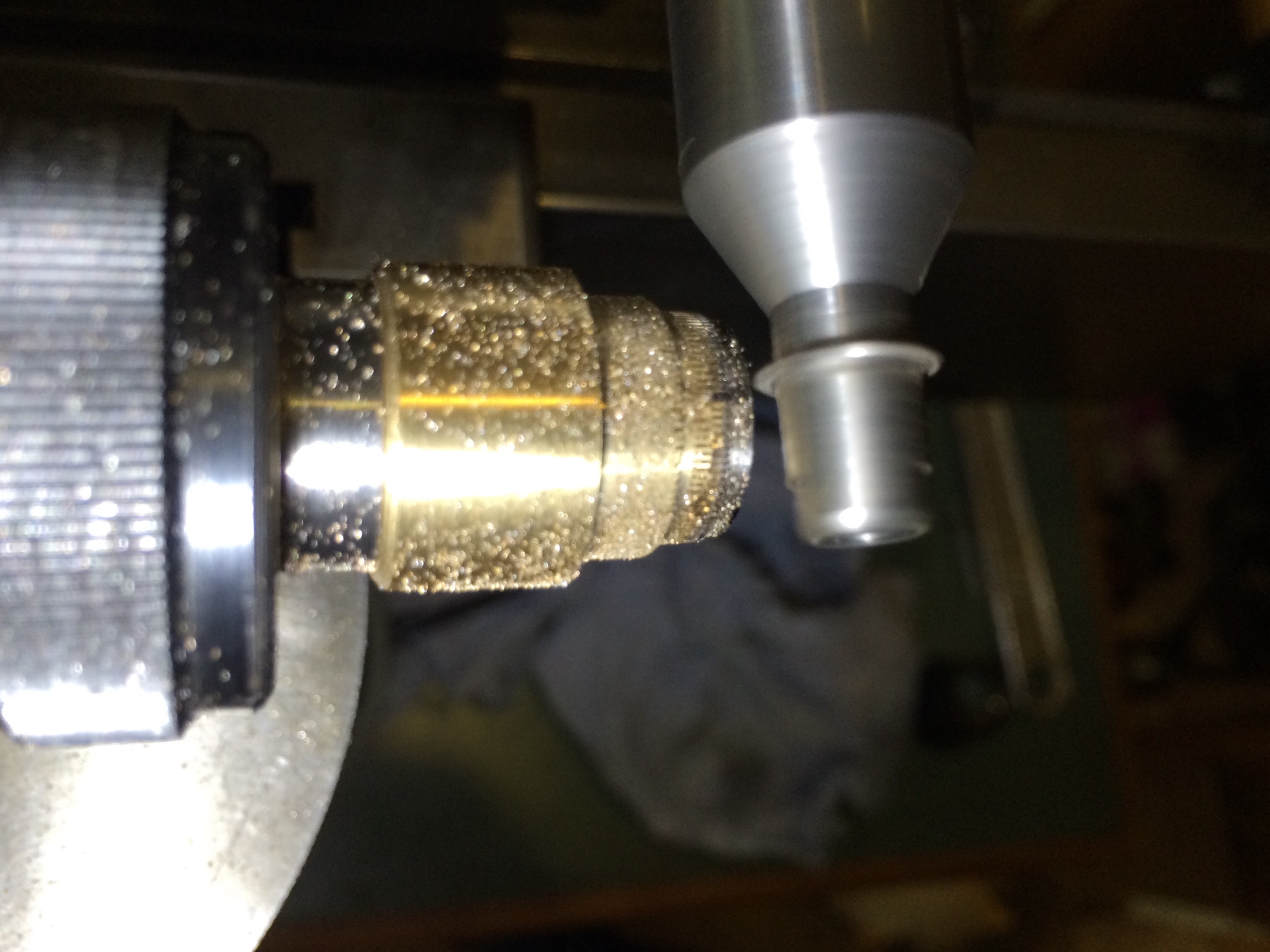
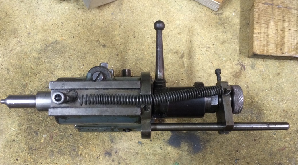
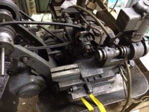
The W12 centring scope was put into the workholding spindle and the cutter centred as accurately as I could, before clamping the gib strip tight. The position of the workpiece spindle would need adjusting later so that the cutter made the correct length of cut. 

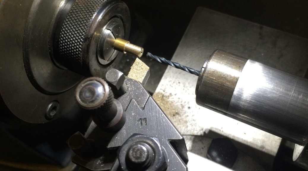
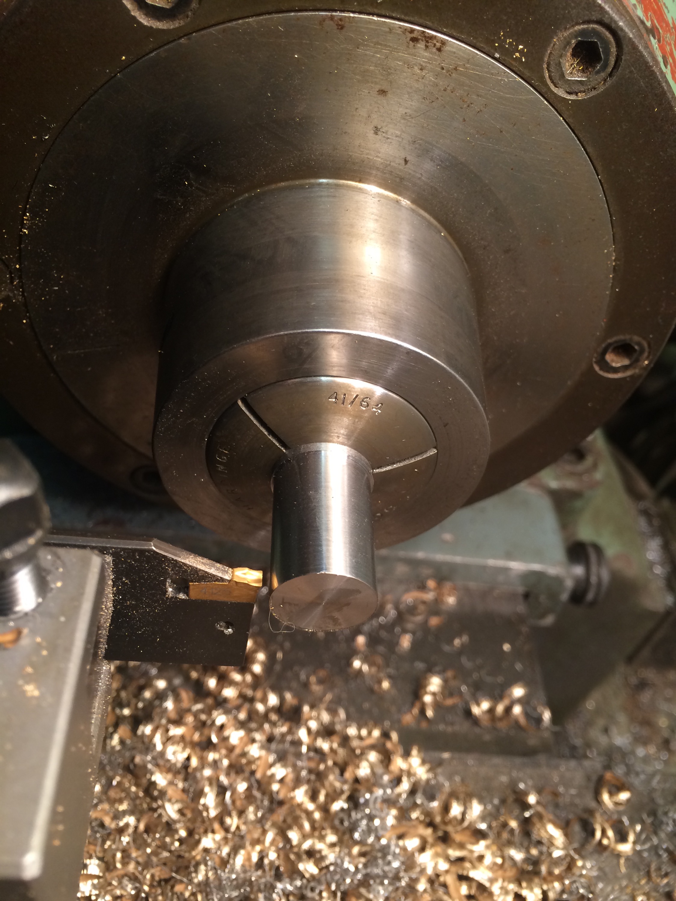
The centring scope was replaced by a collet holding a brass blank; brass was used for this and subsequent trials so that full depth cuts could be taken in a single pass.


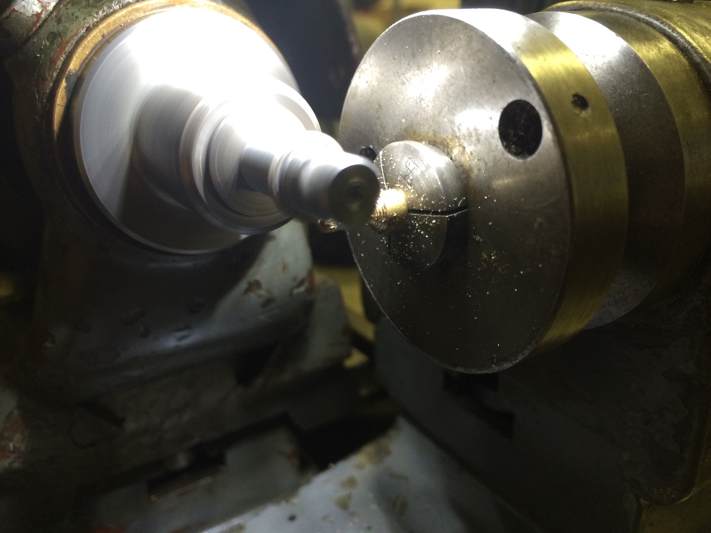
The result was very satisfying, with good centring of the cutter achieved after a few minor modifications of the cutter axis position. 
   

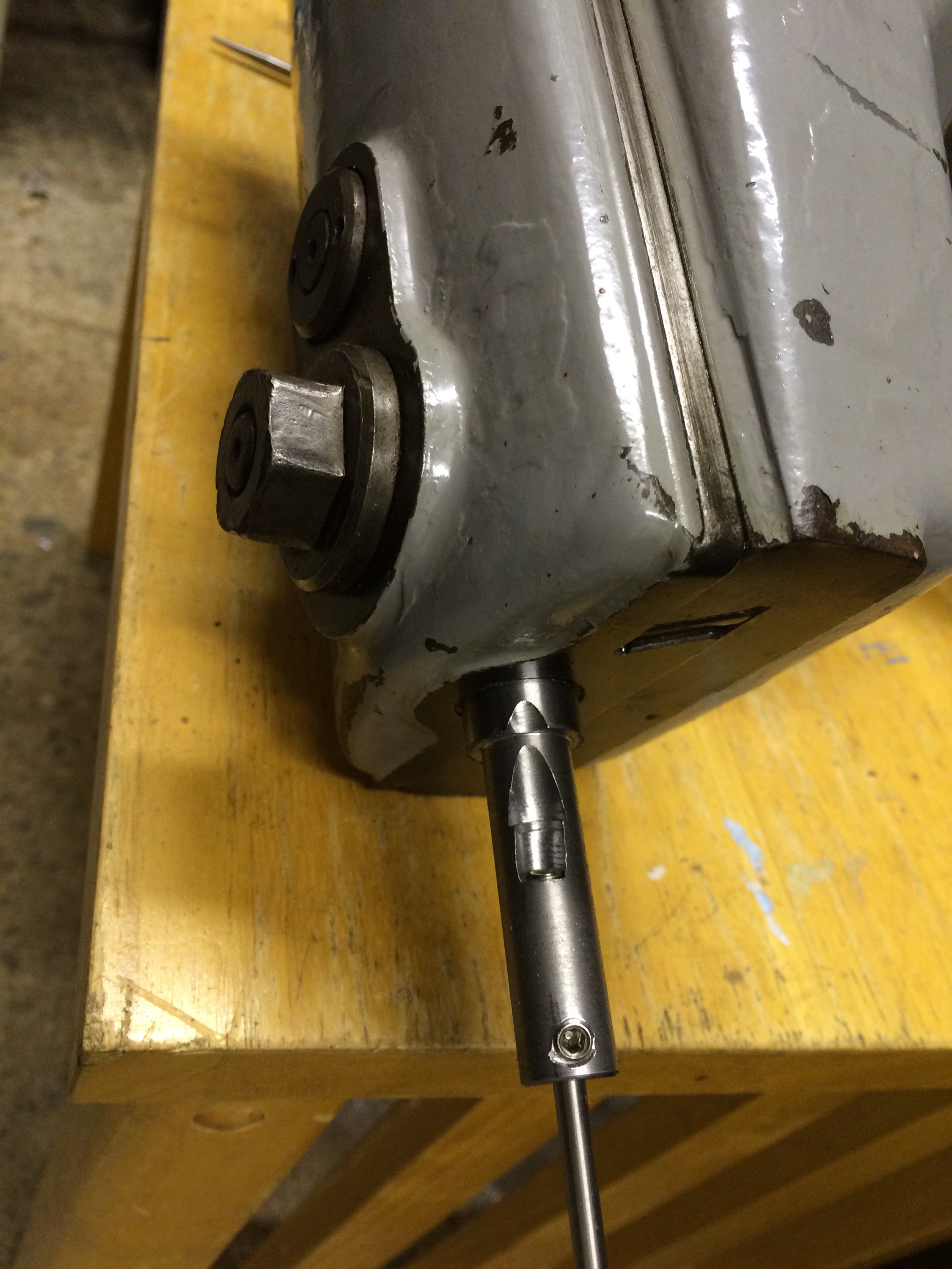
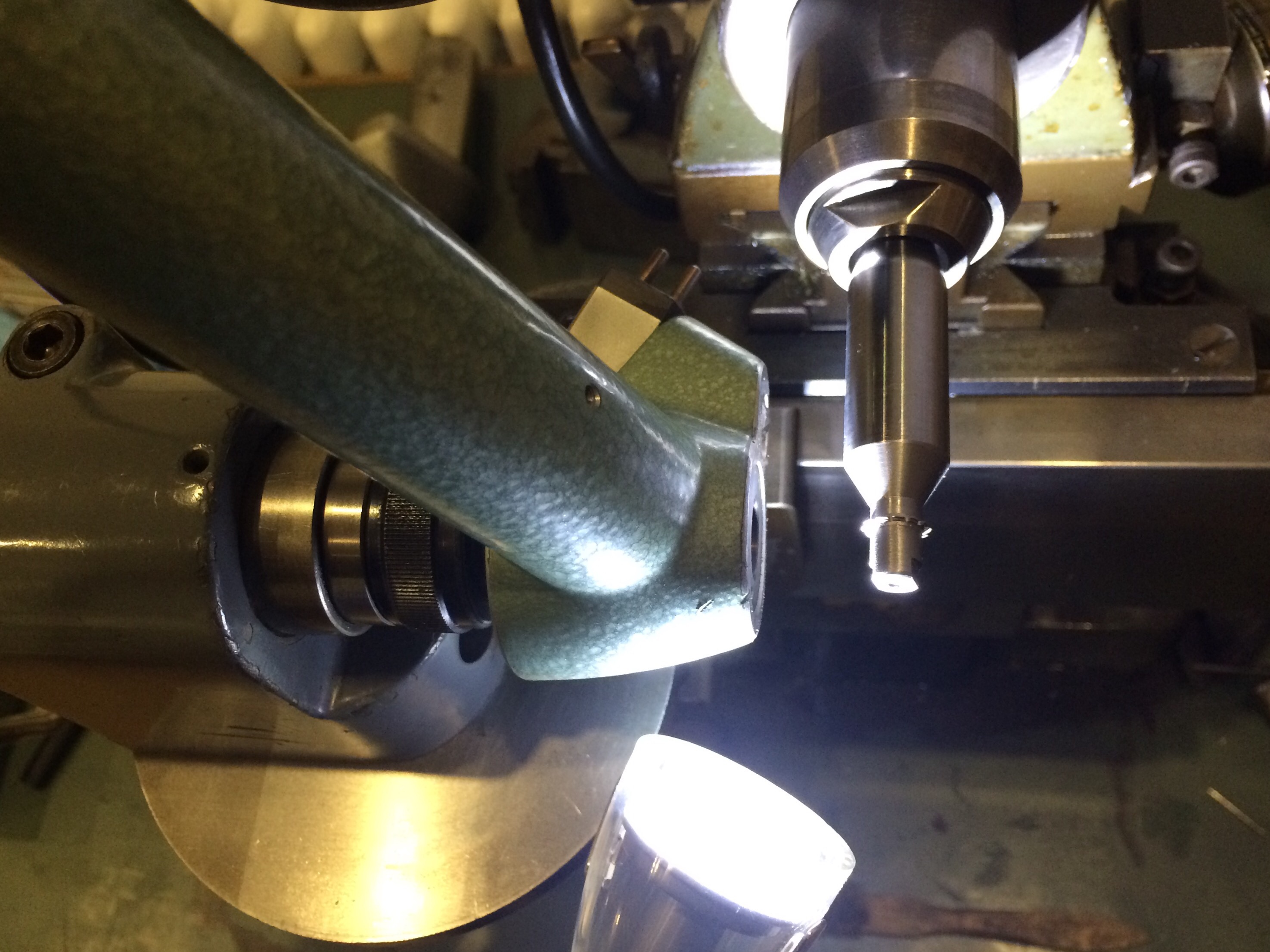
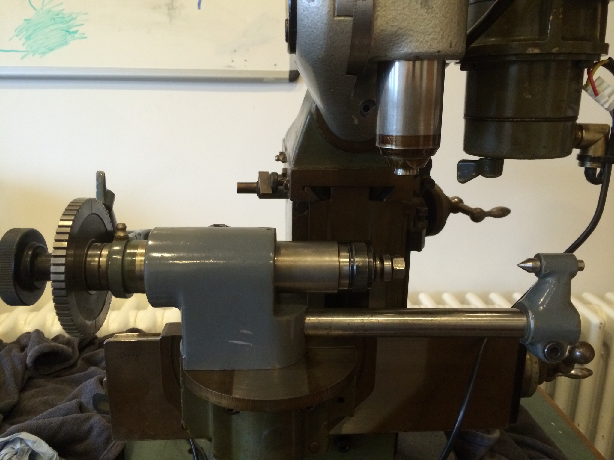
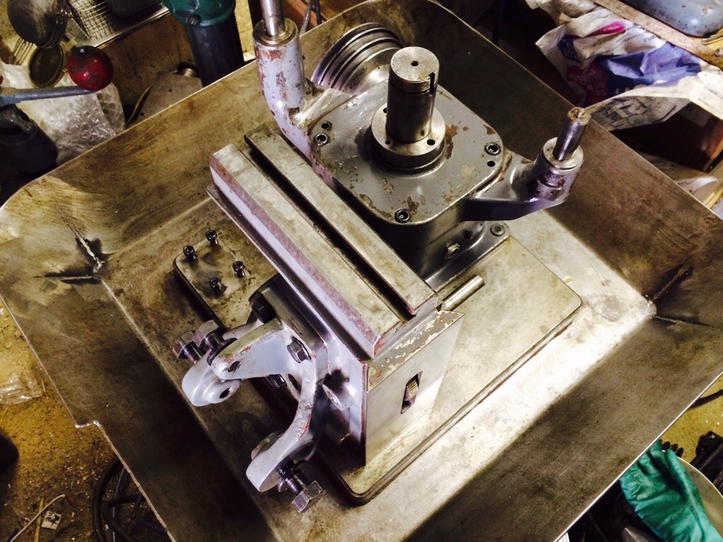
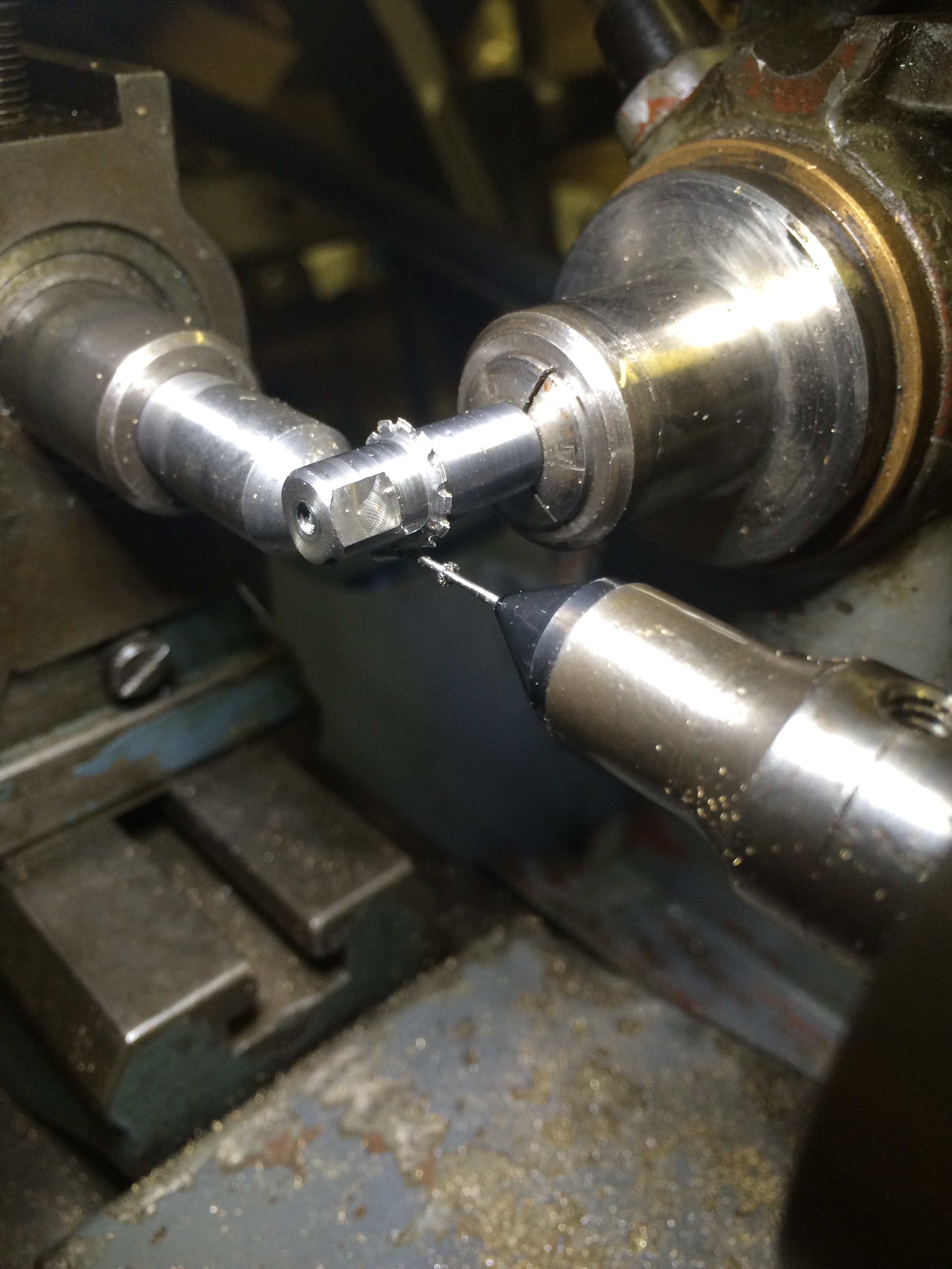
Since the pinion blank was being prepared on the lathe and then transferred to the pinion cutter, I decided to set up for cutting between centres. This should help maintain concentricity of all the various operations. I also decided to start using the power feed on the cutter axis, so that the cutter moved out of the way after the teeth had been cut. 

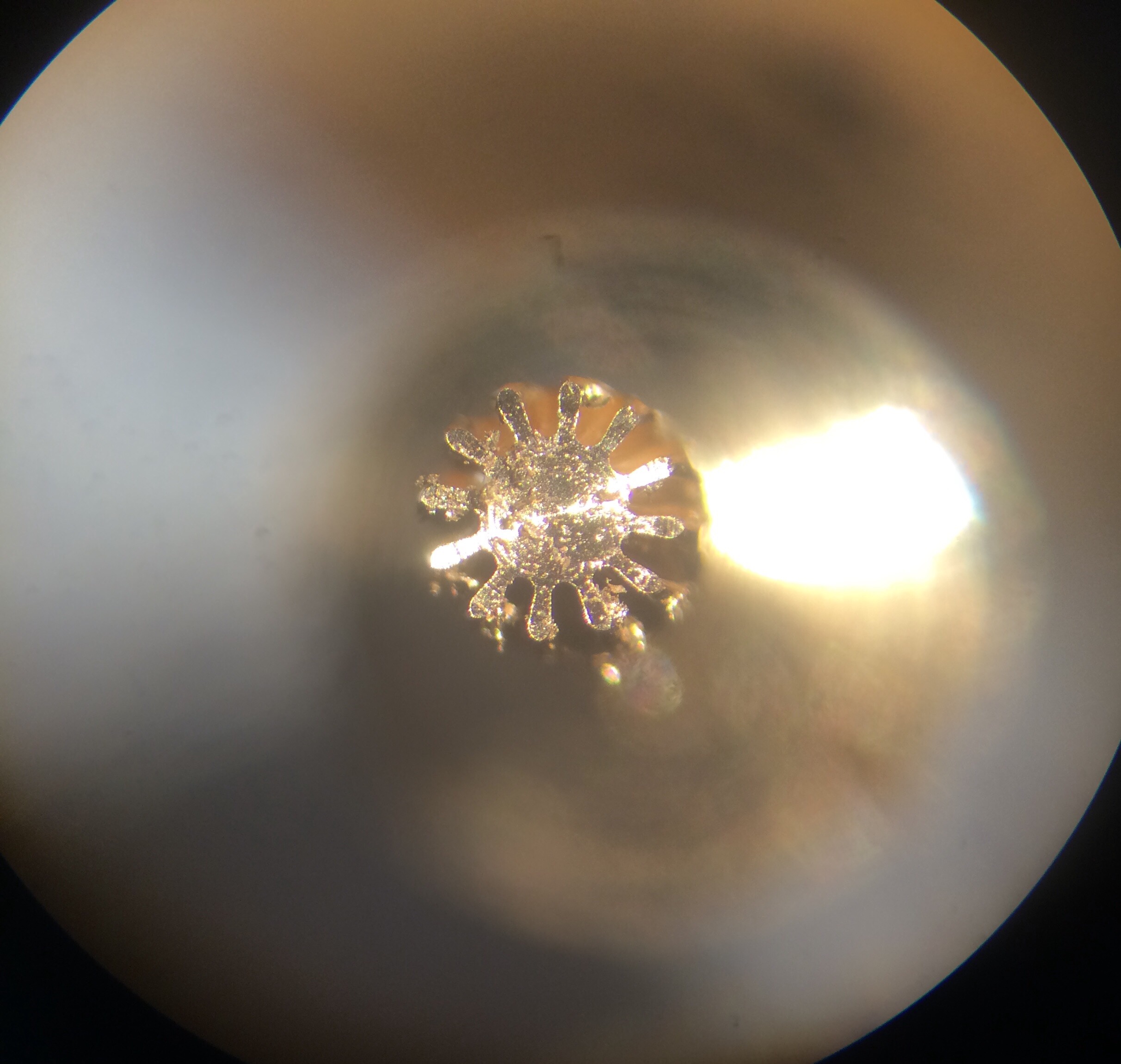
A few unsuccessful trials with uneven leaves led me to suspect that something was up with the alignment of the tailstock, the movement of the cutter axis, or even both:
 

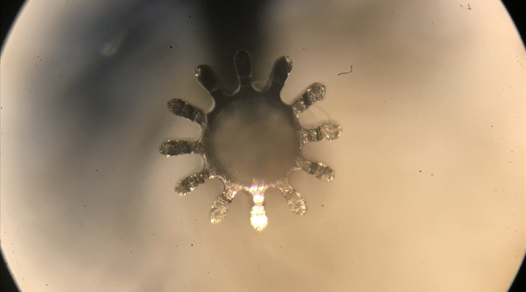
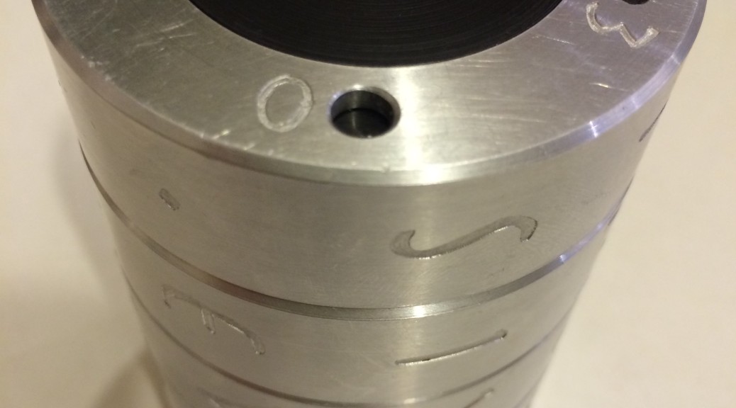
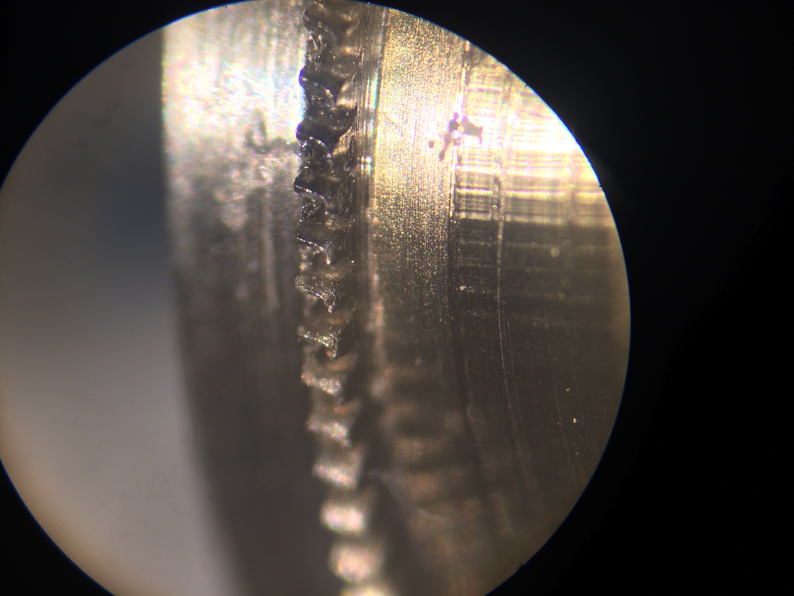
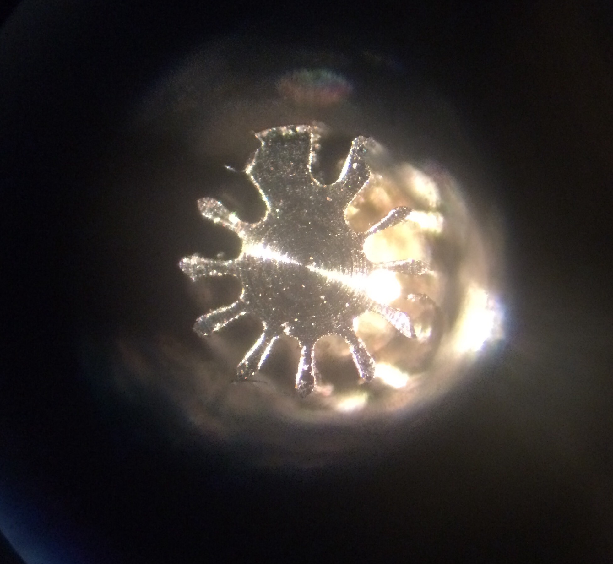
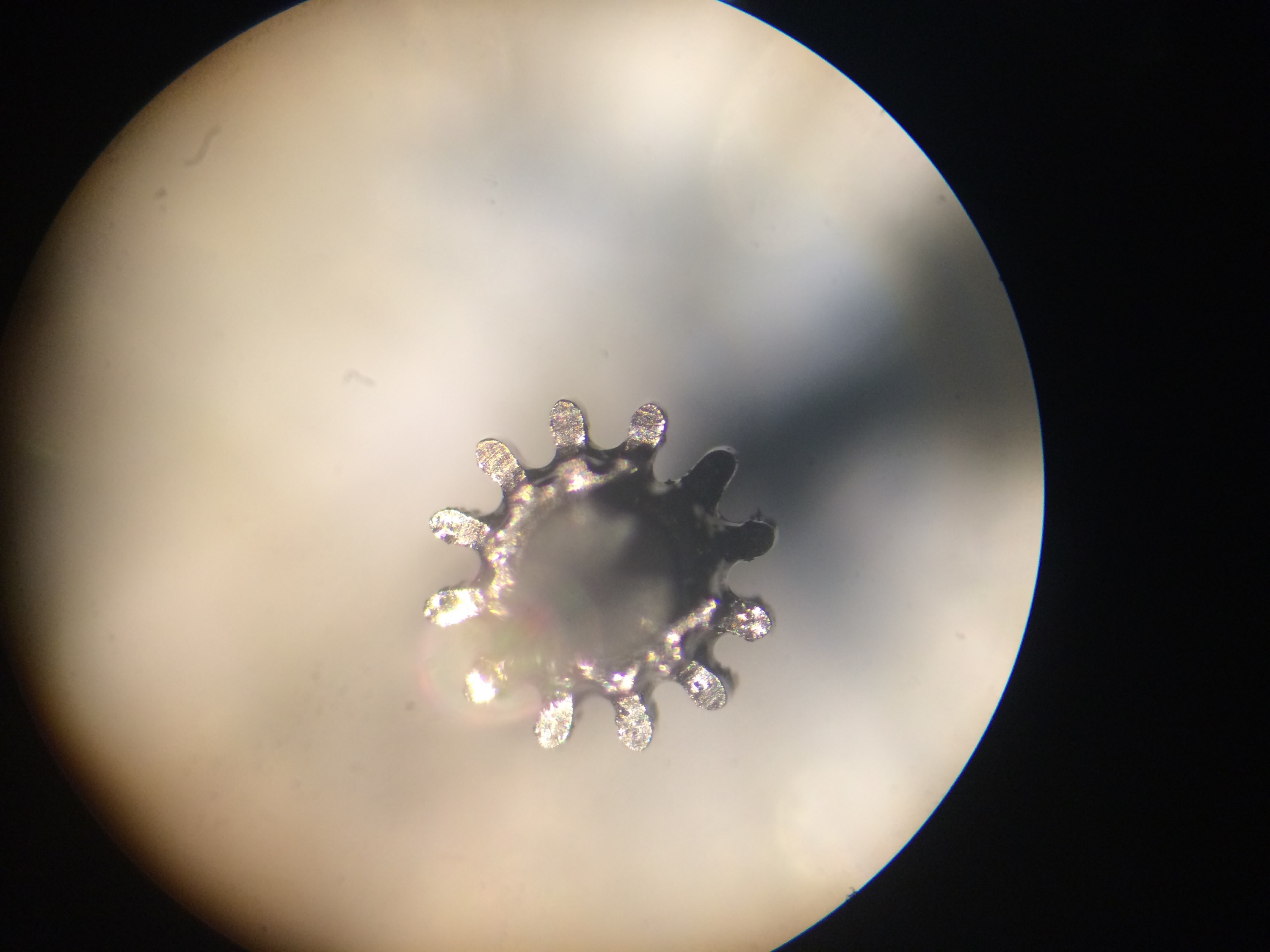
It didn’t take long to realise from a side view of the pinion that the tailstock was off centre, giving a helical pinion. What was harder to spot was the pattern in leaf irregularities; in the above photo every 4th leaf is much more deformed than its neighbours (see the leaf at about 11 o’clock). This could only mean one thing: the lobes in the driving cam were uneven. 
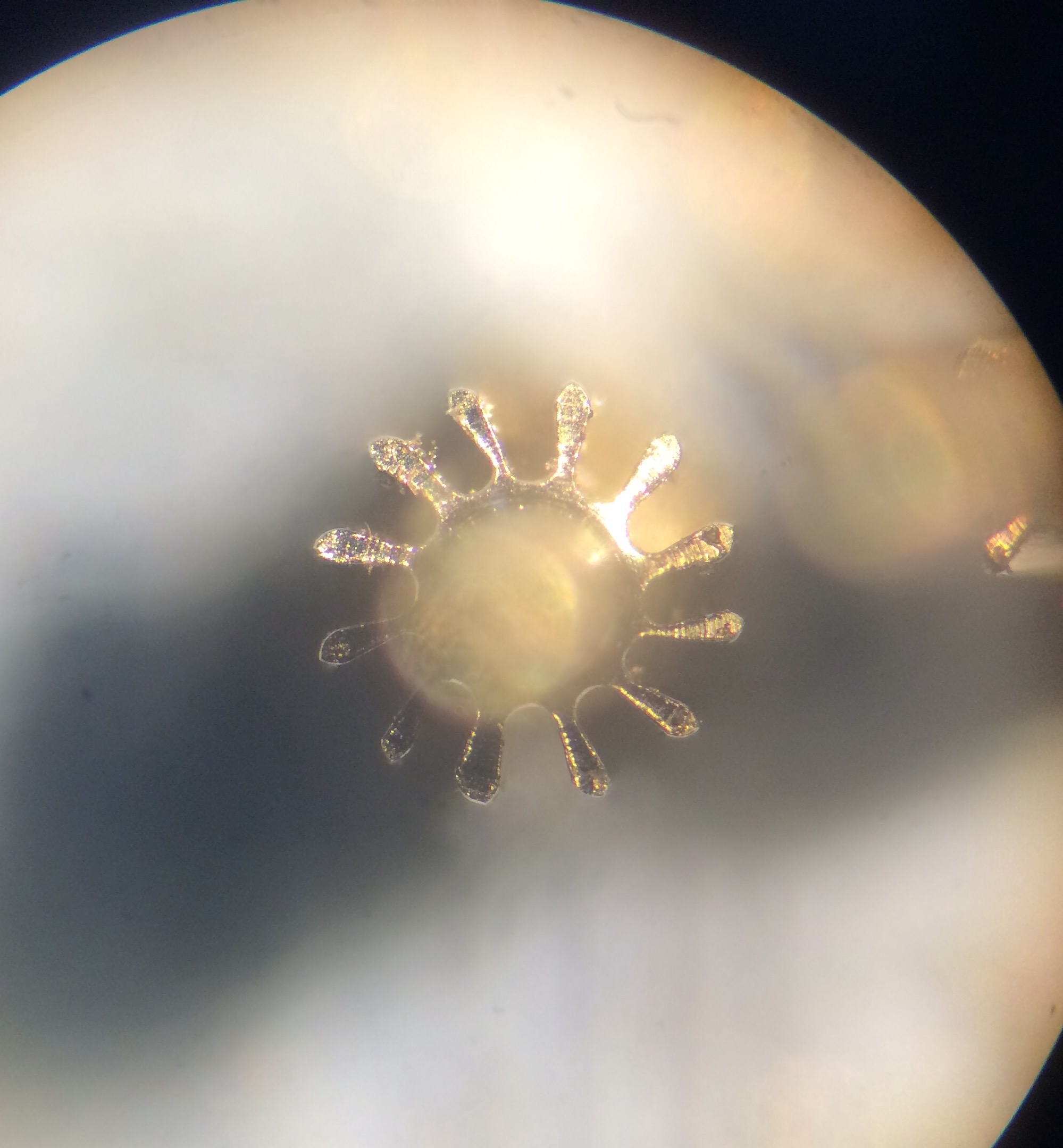
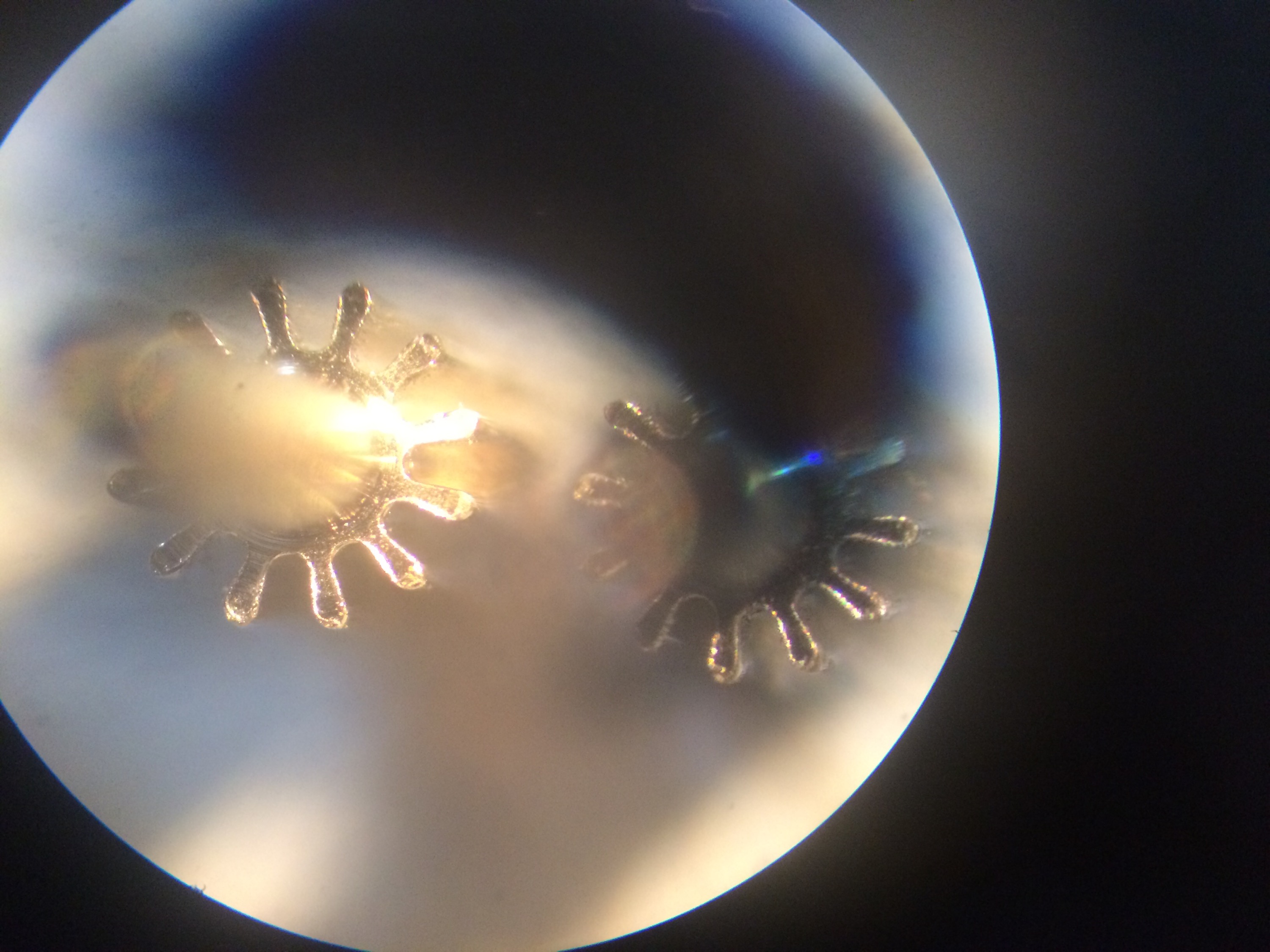
Once I established that the cam that drives the cutter axis forward has lobes of different heights and was therefore causing the cutter to be off-centre for 3 out of 4 the cuts, I decided to lock this axis once again. Again the workpiece was held in a collet and again it was simple to centre the cutter as the cutting progressed around a trial pinion; the final leaf cut appears at about 10 o’clock in the following photo:


The depth of cut is quite possibly not correct in this trial but since the blank wasn’t accurately turned to size this isn’t a fair test piece. 
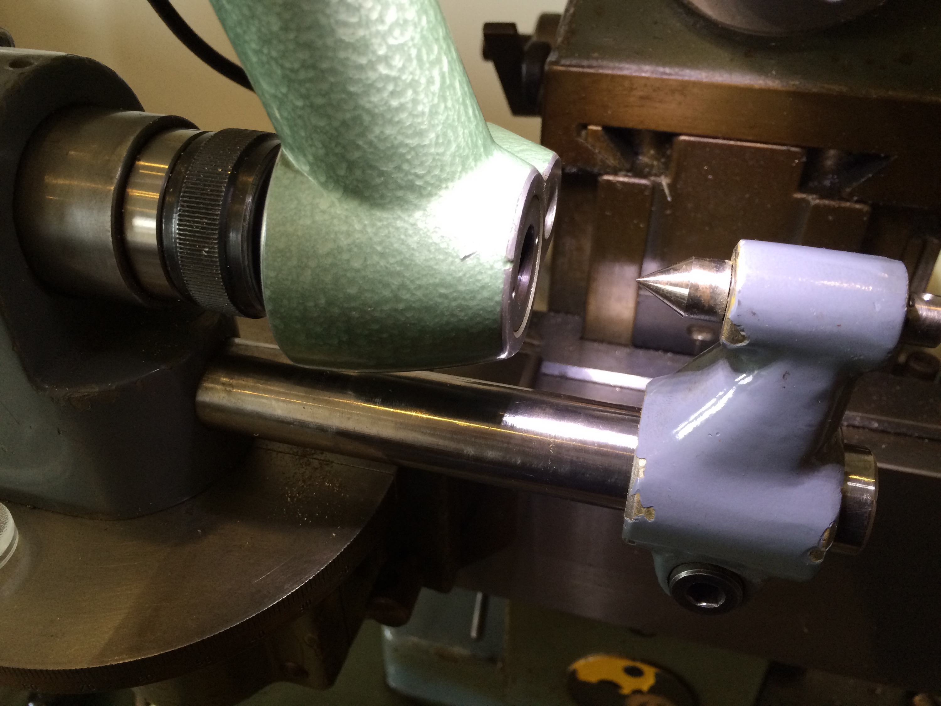
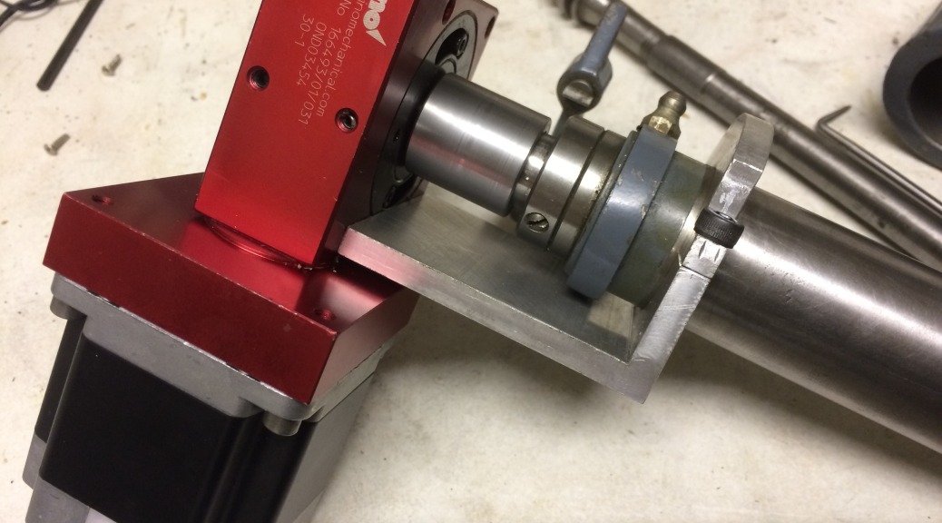
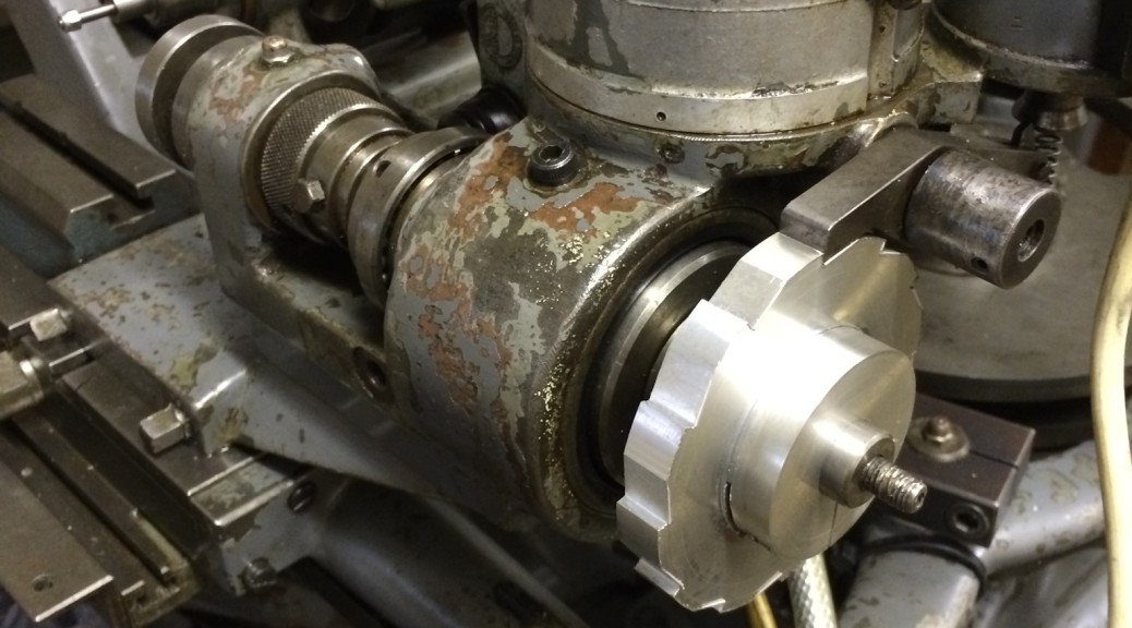
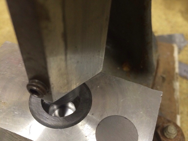
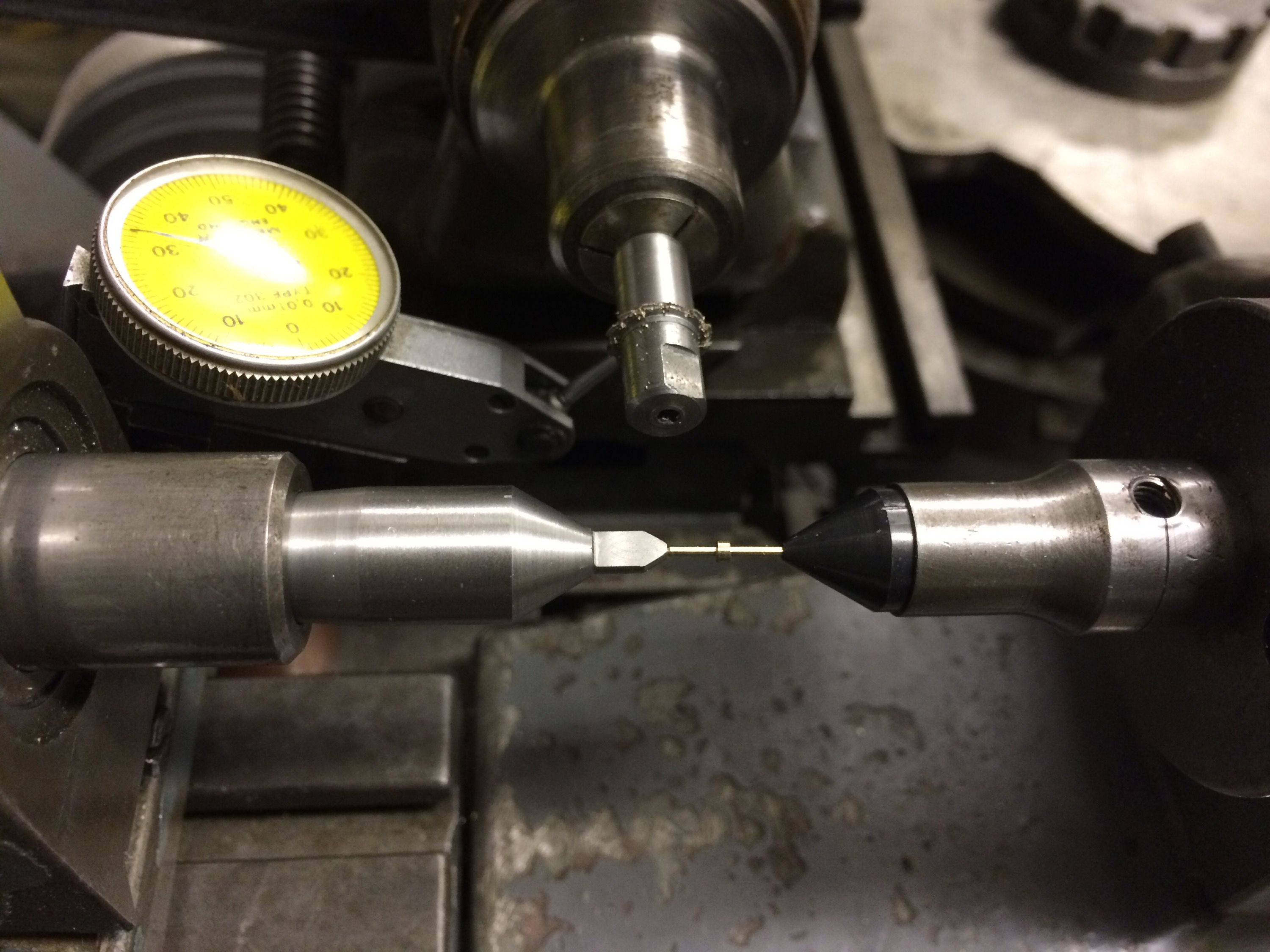
Next step was to get the tailstock centred and take some more test cuts between centres, still with the cutter axis locked. This did make extracting the pinion somewhat tricky but means I get accurate cuts, so this is a price worth paying until the uneven loves on the cam can be sorted. 

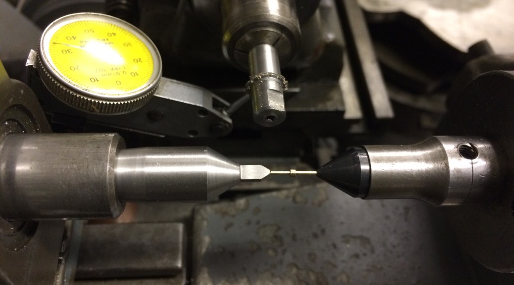
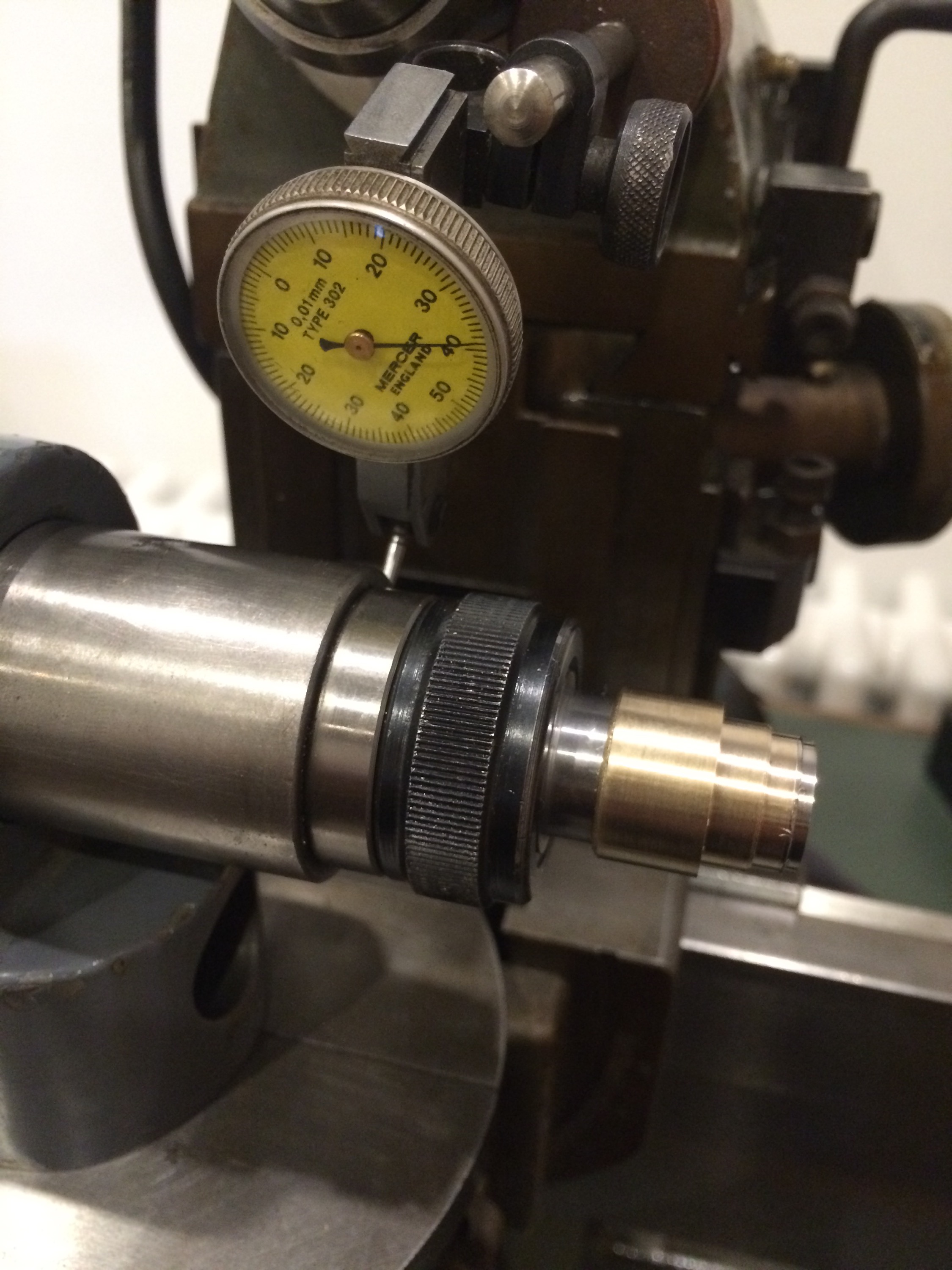
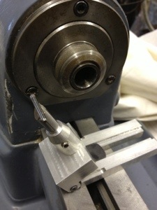
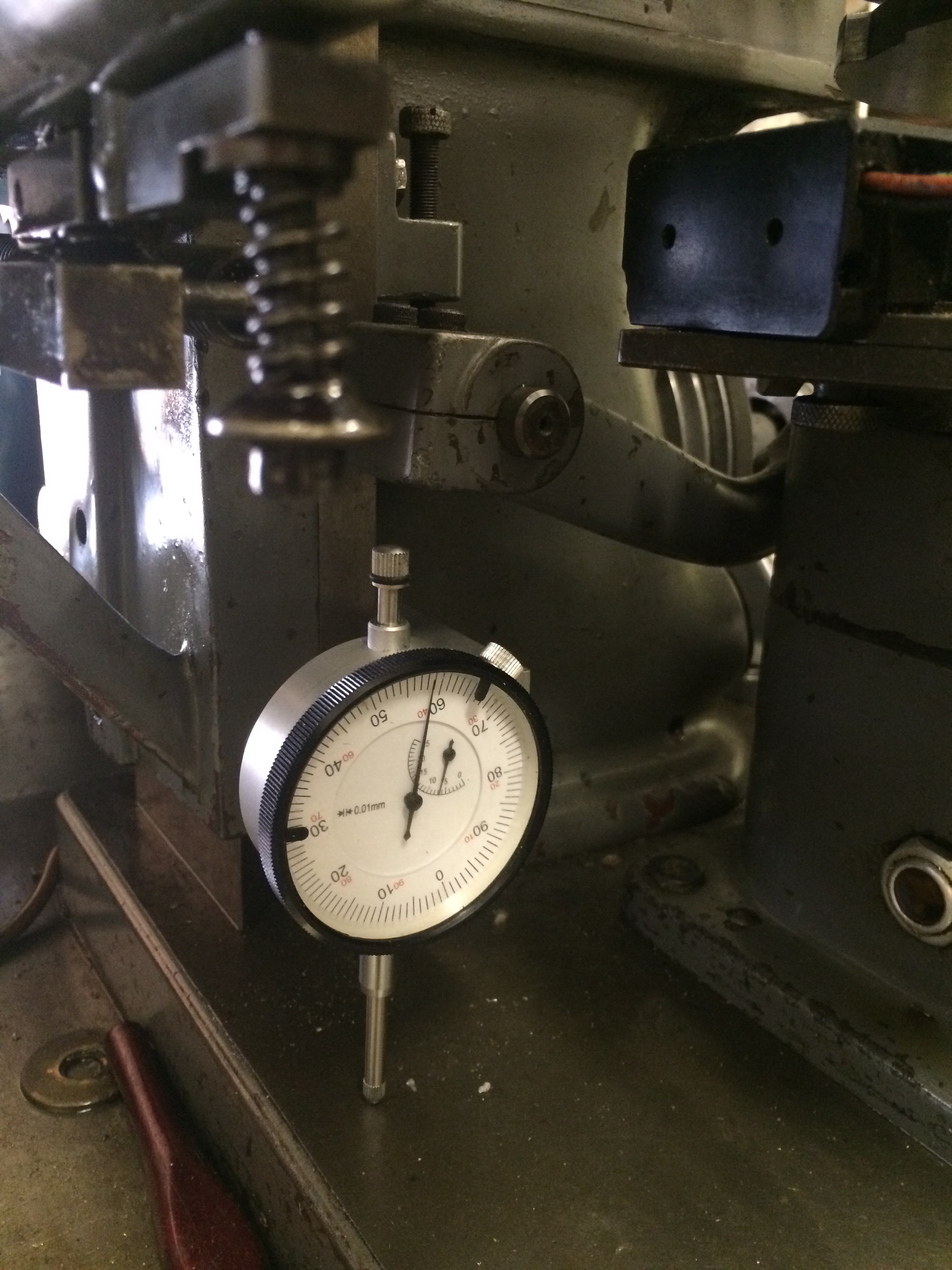
The tailstock was relatively far off centre to begin with and is still not quite there in the photo below, probably something like 0.01mm off. Adjustments were made with a dial indicator against the side of the centre so that the movement could be accurately measured. 


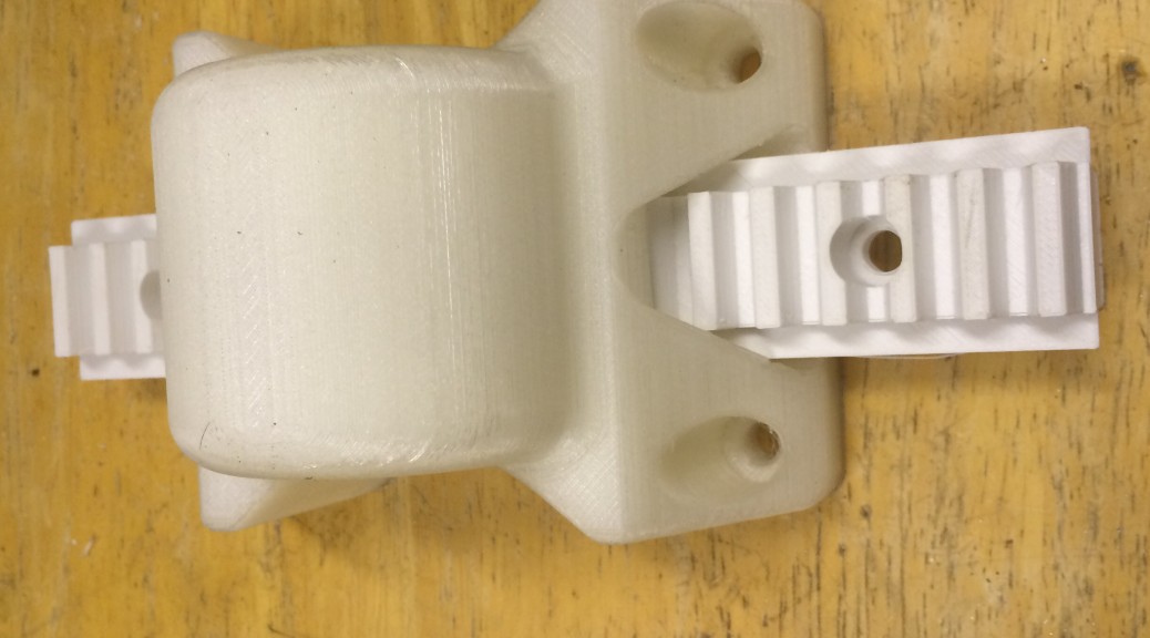
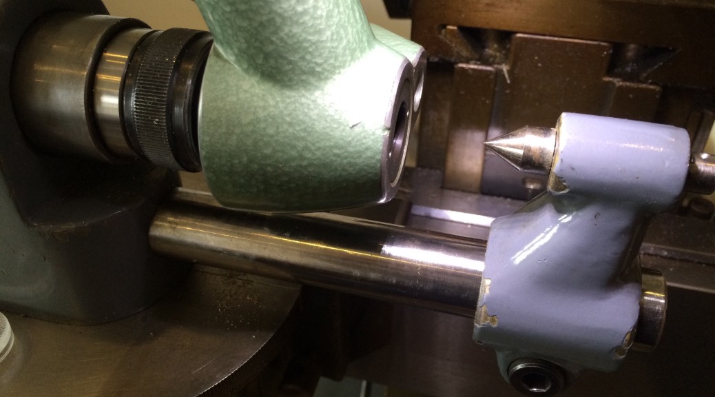
Before trying a steel pinion, which would need multiple cuts at measured depths, I decided to add better control of the Z axis. My first attempt was to replace the current fine pitch screw adjustment with a micrometer head. I made up a bracket to hold this but then struggled to get it actually attached to the machine because of limited clearance. In the process of doing this I moved the cutter axis to get it out of the way. Eventually I opted for using the original screw but adding a dial indicator so that I could at least measure the changes being made with the screw:
 

After realigning the cutter by eye, I made a test cut in brass. My guessed alignment turned out to be about 0.01mm off, so after a minor adjustment I had the machine ready to go. In the photo below the first cut is at 12 o’clock, continuing clockwise. 
 

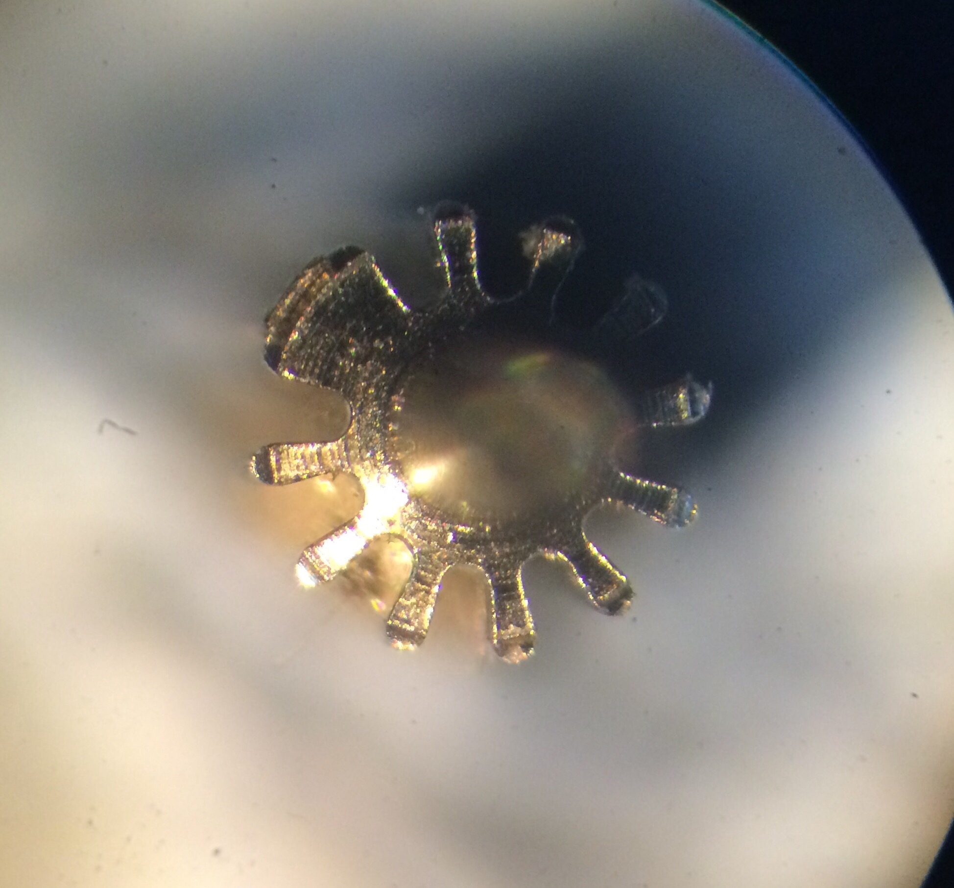
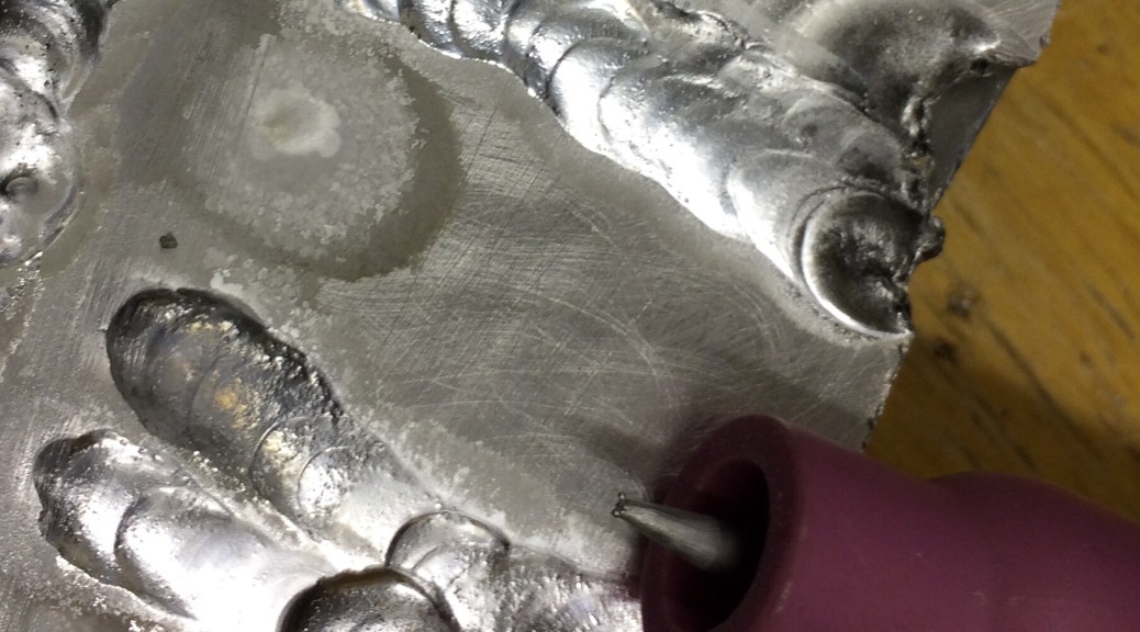
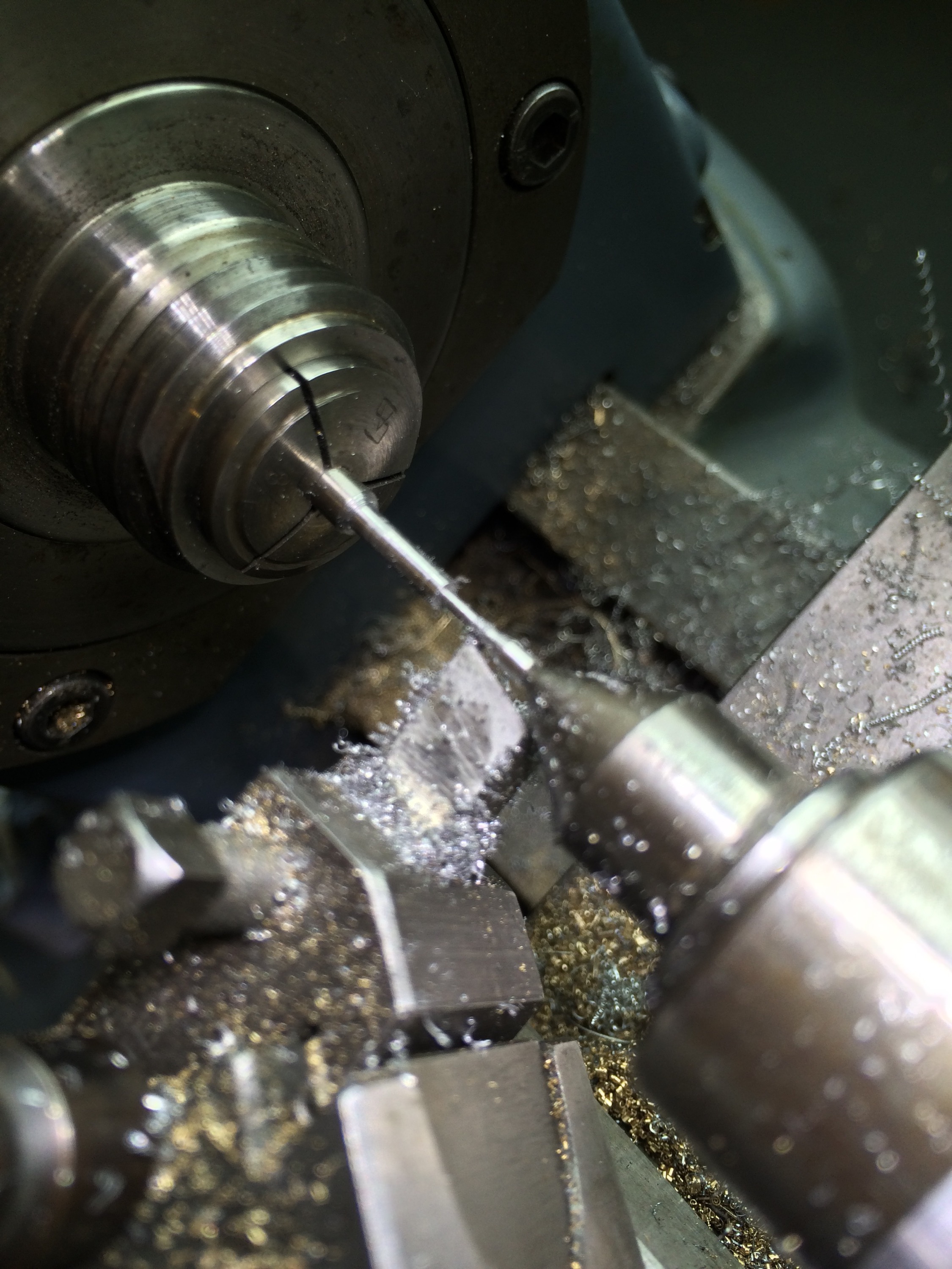
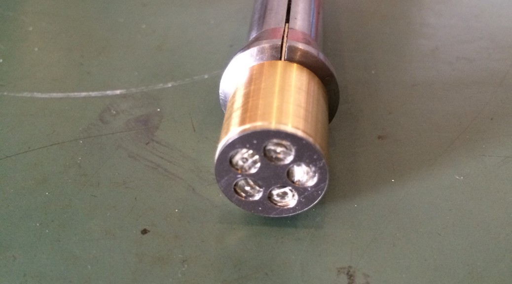
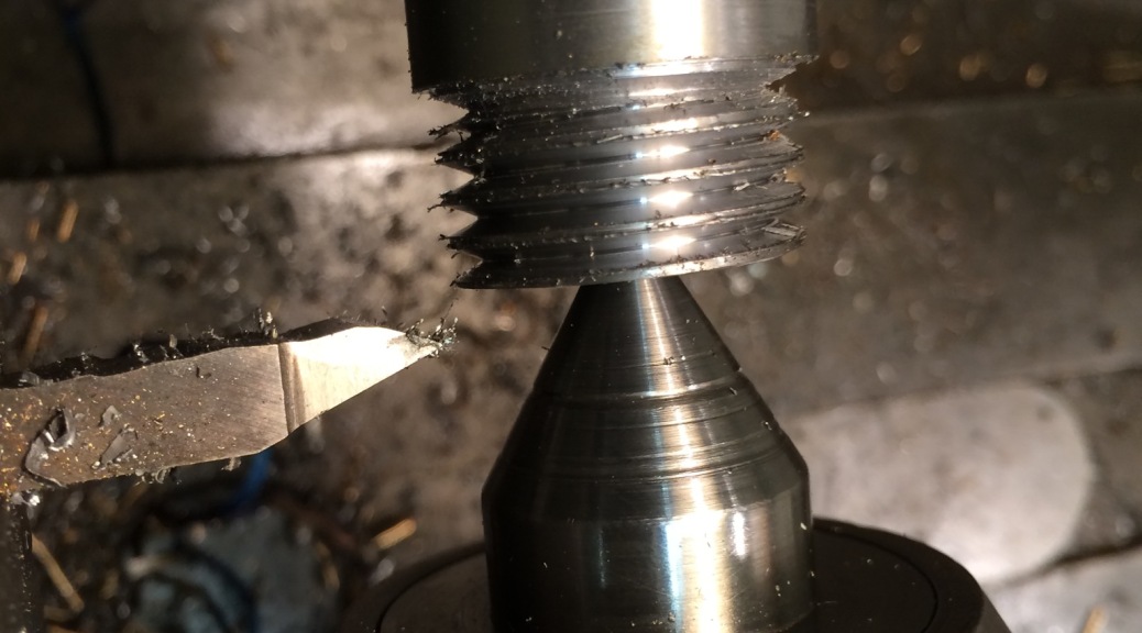
Then it was time to try cutting a steel pinion. The blank was prepared on the Schaublin 70 to fit between the centres, the depth of cut set at 0.1mm, the speed set to about 400rpm and the cutter and pinion blank covered in cutting fluid. Here it is after the third pass.   
 

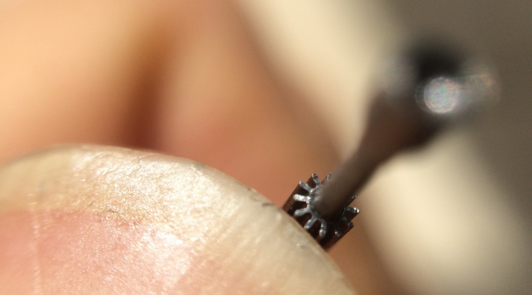
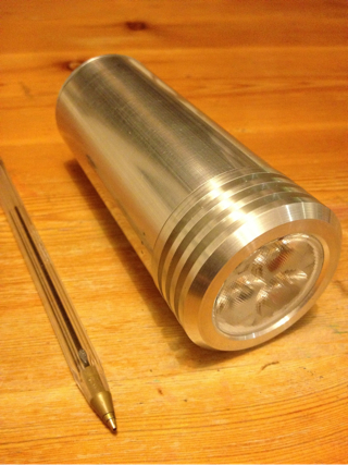
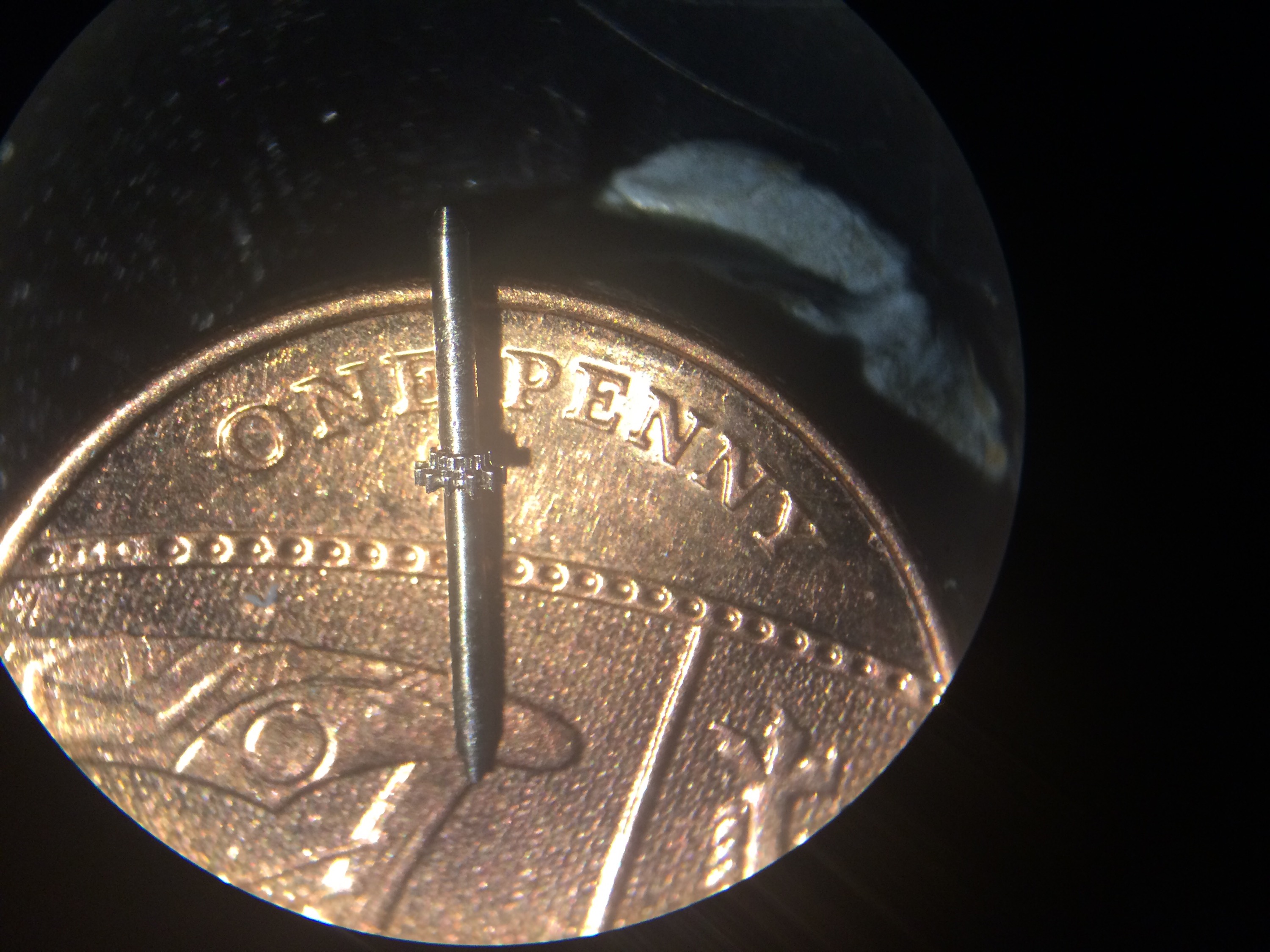
The result was very pleasing:


And sitting on a new penny for scale:
  

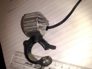
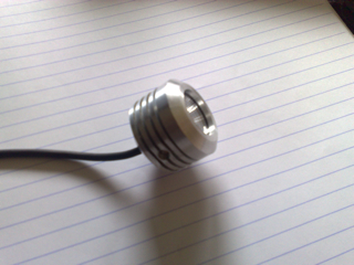
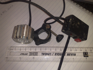
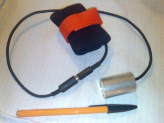
I now have a small USB powered pond pump that I plan to use for pumping a constant stream of cutting oil over the cutter when cutting steel. Ideally this would be powered from the Hauser itself so that it is only on when the spindle is powered, however adding this complexity this can wait. 

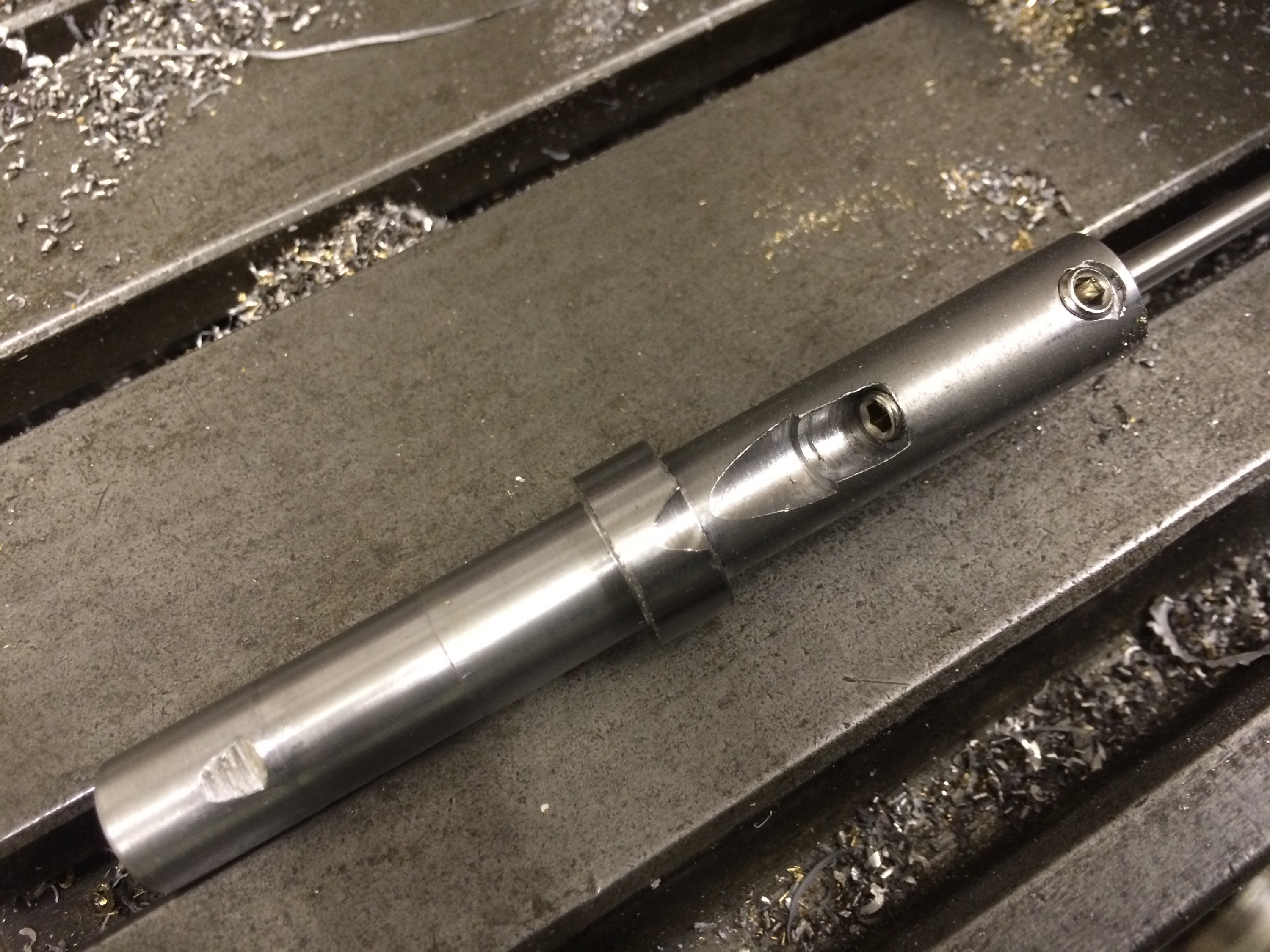
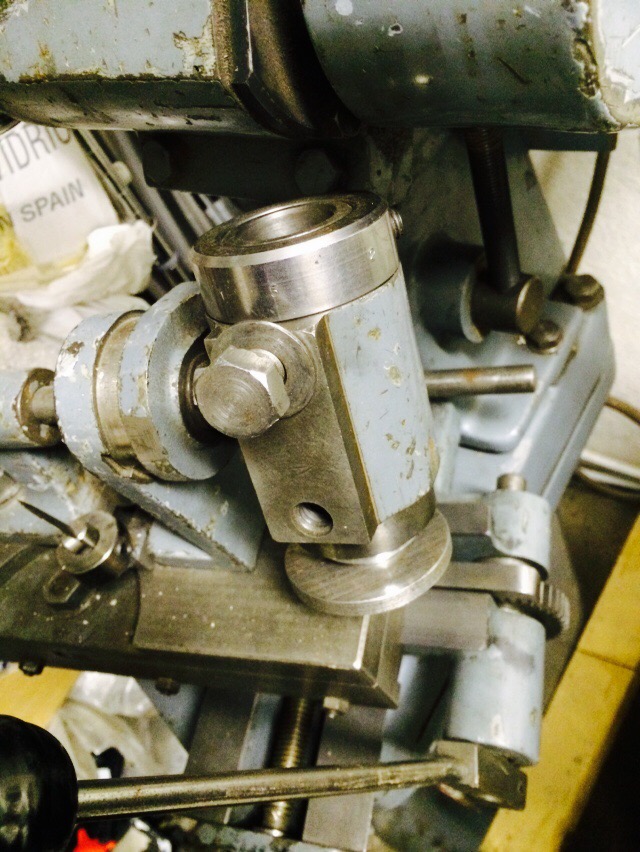
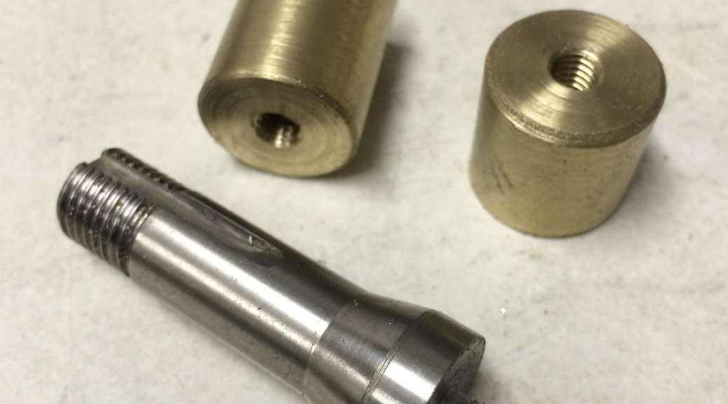
Unfortunately the “I’ve done it” feeling was relatively short-lived… Once I’d made a few pinions for the 4th wheel I moved to making some for the 3rd wheel, which are a fair bit longer. This additional length made any offset between the tailstock and headstock much more apparent, resulting in helical teeth. To cut a relatively long story short, I eventually discovered that my female drive centre (described earlier in this post) had about 0.04mm runout, easily enough to totally mess up a 0.14 module pinion. I initially put this down to runout in the Hauser work holding spindle or the adapter that fits in the spindle to take W12 collets. However, after a period of about 2 months of inactivity in the workshop (but a fair bit of thinking about the problem), I took the centre and put in back in the Schaublin 70 to check whether the runout was an artefact of the centre or the Hauser and it was very obvious that the centre was at fault. Time for a new female drive centre. 

Aligning the centring microscope

I had been having problems when trying to cut pinions, ending up with misshapen leaves as if the cutter was off centre. The centring scope had been used to centre the cutter each time so this was suspect number one. 

A quick search on the web for the maker of my scope, Aubert, revealed they were still in business. They even provide instructions for their current scopes on their website (http://www.marcel-aubert-sa.ch/produkte/anleitung/anl_pdf/anl_mik/m02_mik_111_118.pdf). 

Initial inspection of my scope failed to find the four adjustment screws, Continue reading Aligning the centring microscope

Making pinions

Various texts describe pinion making as being tricky, requiring a very rigid setup to have a chance of success. The Aciera F1 is provides just such a setup. 

The first pinion I cut was for the third wheel. This is a very short pinion but I decided to only turn down one end of the O1 bar, leaving the end that was held in the collet as thick as possible to increase rigidity. Since the indexing head on the F1 only had a male centre, I left a long pivot and drilled a small hole in the end to be supported by the male centre. 


The F1 was prepared for pinion cutting by centring the indexing head on the cutter:
 

And aligning the male centre:

The blank was transferred to the F1 for the leaves to be cut. The full depth of 0.41mm was reached in four cuts, feeding using the leadscrew as recommended in the J Malcolm Wilde text. 

Puzzle number 2

A few years ago I made a mechanical puzzle for a friend, with 5 aluminium rings around a cylindrical aluminium core. Each ring had a pin protruding from the inside that engaged in a slot in the core and all each ring was joined to its neighbours so that each could rotate independently but all had to move along the core together. The aim was to remove the core by twisting the rings and it was just a case of mental Continue reading Puzzle number 2

Third wheel

The third wheel is the smallest in the going train of my watch, with 90 teeth. The process for making this was:

1. Cut a wheel blank out of 0.2mm titanium sheet.

2. Attach the blank to a brass wax chuck with superglue and turn down to the wheel full diameter on the Schaublin 70 lathe.

3. Set up the Aciera F1 so that the end of the electronic indexing spindle was facing the horizontal spindle so that the 5 circles could be cut Continue reading Third wheel

Aciera F3 vertical head

When I bought the F3 it came with a just the high speed vertical head. While this has been very useful so far, its speed range of 1000-6000 rpm suggests that it is best suited to small cutters and probably not the right thing to use for milling large pockets or hard materials (1000 rpm is just about ok for an 8mm carbide end mill in steel). My searching for a vertical head was finally rewarded (even though it’s not the Continue reading Aciera F3 vertical head

Clarkson Mk1 Tool & Cutter Grinder

This grinder was picked up for not much at an auction but since then has sat in the workshop unused. My plan is to use it for sharpening end mills and also for shaping and sharpening lathe tools. 


It came with a few accessories including the centres visible in the photo above and the universal head. 


Unfortunately the head only has one sleeve, shown removed in the photo below. One plan is to make a new sleeve, 1 1/2″ OD to fit the Continue reading Clarkson Mk1 Tool & Cutter Grinder

Spindle problems with the Aciera F1

The faff to get everything set up for wheel cutting seemed endless: even after fitting up the electronic indexing head to the spindle I made a W12 wax chuck, then machined a blank arbour to take the cutter and made a nut to clamp the cutter in place. I used a dial indicator to set the indexing spindle perpendicular to the cutter axis:

(null)

Then put the centring microscope in the indexing spindle in order to get the cutter dead centre:

(null)

It was at Continue reading Spindle problems with the Aciera F1

Materials

My choice of materials is likely to be different to most. I have a fascination with titanium, for no particular reason other than liking the appearance and weight.

My first experience of machining titanium was a commission from a friend: I mentioned to him that I fancied making something from titanium, in response to which he asked me to make him a wedding ring. My first attempt (which turned out to be too large) was in grade 5, the final ring Continue reading Materials

Mandrel for wheel cutting

I wish to cut multiple copies of the same size wheel in one go, so that I have spares in case of in inevitable mistake, and also so that I may end up with most of the parts for more than one watch with little additional effort. This means making up a mandrel to hold multiple wheel blanks for the wheel cutting process, instead of just using a superglue arbor for a single wheel.

The design of my wheels, with circular Continue reading Mandrel for wheel cutting

Making a W12 wax chuck

In order to hold various parts, such as the barrel and balance wheel, for machining, I wanted a wax chuck. I briefly considered making a brass copy of a W12 arbor but decided that was going to be a lot of work and difficult to get accurate. After all, part of the idea of the wax chuck is that I can swap the part between the Schaublin 70 lathe and the Aciera F1 mill without losing concentricity through any remounting.

Eventually Continue reading Making a W12 wax chuck

Worm drive for wheel cutting on the Aciera F1

At last, more progress on the tool making. After breaking the cutting tool while making the hob for the worm wheel, I started looking around for off-the-shelf worm drives. A low backlash one came up on eBay for $100 including a stepper motor, so I jumped.

My original plan with the bought drive was to bore out the centre of the worm wheel so that it would fit on the spindle of the direct dividing head (or indexing head) of the Continue reading Worm drive for wheel cutting on the Aciera F1

Making a worm drive – making the hob

After some deliberation, I decided that I would attempt to make my own worm gear and wheel for my electronic indexing device. While it’s possible to buy the gear and wheel from companies such as HPC, the low backlash type that I want commands a high price. Besides, it’s an interesting project in itself.

Some searching on the web got me the basic calculations for the sizes of gear and wheel, based on my desired ratio of 36:1. This ratio was Continue reading Making a worm drive – making the hob

Barrel

This is the first component I started to make for this design of the watch. The barrel itself is relatively simple, the complicated part I think will be making the arbor. I have chosen to make it out of commercially pure grade 2 Titanium; this grade has been chosen as I believe it is easier machining than the commonly-available grade 5.

I put a length of 16mm diameter titanium bar in the Hardinge and faced the end perpendicular. This face will be stuck to the ‘wax’ chuck with superglue so needs to be flat. A few blanks were parted off at 2mm thickness ready to be turned to size on the Schaublin 70.

IMG_5586.JPG

I was very pleasantly surprised to discover how well the grade 2 machined with a sharp HSS cutter. I have previously worked with grade 5, which I remember as requiring more careful handling.

The titanium blank was then stuck to the wax chuck with superglue ready to turn the outside to size for the tips of the teeth and turn a shoulder so that the body has a smaller diameter than the teeth. At this point I had two choices:
A. Centre drill and bore out the inside to size for the main spring, make a 5 degree undercut lip into which the lid will snap and bore the arbor pivot to size; or
B. Move the wax chuck to the Aciera F1 and start cutting the teeth.

Instinct told me that option A was the better one in terms of maintaining concentricity by minimising transfers between machines, however eagerness got the better of me as I was keen to make my first attempt at cutting teeth. 

The Aciera F1 was set up for wheel cutting using the electronic indexing head (see here and here for more details). 

  
The indexing head was checked for alignment with the mill X axis and centred relative to the cutter, then it was ready for cutting teeth:


After successfully cutting all 96 teeth in two passes (0.25mm and 0.16mm depth to minimise the load on the cutter) the barrel on its wax chuck was returned to the lathe for boring. 

However, it was at this point that I discovered an earlier error that would consign this barrel to the scrap bin: I did not measure the thickness of the blank accurately before attaching it to the wax chuck. The problem then was that I couldn’t determine the thickness of material remaining during boring. In an attempt to rectify this error, I used a left hand turning tool to cut a groove behind the barrel, gradually widening it until I was cutting superglue and titanium instead of brass. A good plan in theory, however theory didn’t match reality and I ended up bending many of the teeth on the barrel:


Next time I shall use a micrometer before getting the superglue out. 
 

Balance wheel

The design for the balance wheel follows that in Watchmaking quite closely, with the exception of the spokes. I may yet give it more traditional spokes, however when I did this design I had recently tried sawing and filing a wheel with traditional spokes and did not want to do that again.

The timing of the balance can be adjusted by rotating the four eccentrically mounted weights on the wheel.

Moving the Aciera F3 into the workshop

One thing is for sure – while the F3 isn’t that big, it is certainly solidly built. Having learned from the effort involved to get the 750kg of Hardinge lathe up the slight incline into the workshop, the F3 was slid onto a length of kitchen worktop with short lengths of scaffold pole underneath as rollers.
IMG_5018-0.JPG

One end of a ratchet strap was looped around the bottom of the base, with the ratchet itself attached to a strong anchor inside the Continue reading Moving the Aciera F3 into the workshop

An Aciera F1

The Aciera F1 is considered by some to be the perfect partner for the Schaublin 70 lathe in the watchmaker’s workshop. Rightly so in my opinion: it takes the same W12 collets as the Schaublin 70, has the same thread on the nose of the indexing spindle and can easily be set up for either precision vertical milling or wheel cutting.
IMG_4996.JPG

I have just got hold of a nice example of one, albeit in need of a clean. It came with Continue reading An Aciera F1

Changes to the workshop – the Aciera F3

Having been keeping my eyes open for a nice Aciera F3, I finally found one
this week. For a change, it was only 40 minutes drive away (most of my machines have involved round trips of around 6 hours or more).

Collection was simple, unloading at the workshop wasn’t that much more complicated. With the aid of a borrowed telehandler, it was lifted off the trailer and posted under a shed ready for moving into the workshop.
IMG_4920.JPG

The next step is to clear space Continue reading Changes to the workshop – the Aciera F3

New cam disks for the Hauser

A quick trip to the local scrap yard got me a piece of 6mm steel plate large enough to make at least two new cam disks for the Hauser. These have been roughed into octagons using an angle grinder, ready to either put on the lathe or a rotary table on the mill.

I still haven’t worked out how to hold them while machining them round. Ultimately they need a 60mm hole through the middle for mounting on the post of the Continue reading New cam disks for the Hauser

Tailstock centre for the Hauser 333

The Hauser came with a tailstock (adjustable in both height and Y position) but with no centre. I had tried various centres in it, including those with small Morse tapers and the Schaublin 2 degree taper, but none fitted. Time to make my own.

I’m sure there must be a good way to copy an internal taper but I opted for trial and error. My Hardinge lathe has a taper-turning attachment that makes it easy to adjust the angle of the taper Continue reading Tailstock centre for the Hauser 333

All-in-one lights

My latest designs have been all-in-one, with the LEDs, driver and batteries all in the same case. The one featured here has 3 Cree XP-G LEDs, 4 lithium ion cells and a driver board from TaskLED.

Prompted by the snow in 2010, I have made smaller versions with a single LED and a single lithium ion cell, which are more suitable for head mounting. Just great for a night ski trip up a local hill after xmas dinner!

A view of the back Continue reading All-in-one lights

Bar lights

Both of my designs used Cree MC-E LEDs, at the time the brightest single package LEDs available. Each emitted approximately 900 lumen and featured driver boards from TaskLED.

The first design:
image7

And the later design, with more effective cooling fins:
image6

Helmet lights

Designed to be compact yet bright enough to ride by, these lights used a driver of my own design and construction, controlled by a PIC micro controller. They featured two brightness levels and a battery monitor to indicate the charge status of the battery. The inspiration for these was partly from the series of adventure races in which I competed (the Challenger World series), where handle-bar mounted lights were not allowed.

For this design, I designed and made up my own surface Continue reading Helmet lights

Electronic indexing for wheel cutting

The basic principle of wheel cutting does not seem complicated. Starting with a blank the correct full diameter for the number of teeth, a cutter is used to shape the gap between two teeth. The workpiece spindle is then rotated by the angle corresponding to the tooth width and the cycle repeated until the desired number of teeth have been formed.

The workpiece spindle rotation is typically controlled either using direct indexing, where a detent acts on a disk with the same Continue reading Electronic indexing for wheel cutting

New ratchet wheel for the Hauser 333

The Hauser 333 was made for cutting gears for street lamp timers, or so I have been told. It does this by having a ratchet wheel with the appropriate number of teeth attached to the workpiece spindle. A worm drive motor is constantly trying to rotate the workpiece spindle spindle through a clutch. The clutch slips until a solenoid releases the pawl, allowing the ratchet wheel to rotate until the pawl catches on the next tooth.

When it arrived in my workshop Continue reading New ratchet wheel for the Hauser 333

Restoring the Hauser 333 mill/pinion cutter

When I collected the Hauser it was in need of some TLC. It didn’t look as though it had been abused, just well used. Bit by bit I dismantled it until just the bare bones remained:

20140522-110856-40136549.jpg
Once the parts had been cleaned, the reassembly was relatively quick and very satisfying. The next photo shows the vertical slide and X axis slides back in place. I discovered that the rack for moving the vertical slide was missing; if I decide I want to Continue reading Restoring the Hauser 333 mill/pinion cutter

Making parts

It’s a small step forward but it feels like I’m making some progress – I’ve made a punch and die set to cut wheel blanks.

The idea of cutting lots of circles from thin titanium by hand didn’t appeal, so I made a punch and die from tool steel. The steel turned surprisingly easily with a satisfyingly good fit between punch and die. The parts were then hardened by heating with a small blow torch and quenching in cooking oil. The punch Continue reading Making parts

New toys

While getting the workshop set up, I traded some of the Schaublin kit for other machines. I picked up an old Hauser mill, model 333, serial number 1, whose previous life was in a factory making timers. Wallace and Gromit would be proud: it’s a wonder of cams and levers.

20131123-172003.jpg

20131123-172018.jpg
My plan is to use it for pinion cutting, perhaps even wheel cutting if I can sort out a sensible way to index the spindle in which the work is held. My Continue reading New toys

Progress update – Schaublin lathe

Having been dabbling in lathe dealing over the past few months while trying to get the bits I wanted for my workshop, I’m now almost back at the point of having a working watchmaking lathe: a Schaublin 70 with lots of accessories. Probably not what most would consider a standard setup for a watchmaker but I think I will be exactly what I want: an accurate and rigid setup on which I can turn fine staffs and cut wheels and pinions. Continue reading Progress update – Schaublin lathe

Latest progress

20130701-221545.jpg

Practical work has been minimal recently due to changing lathes from a Pultra setup to a Schaublin setup. This has meant making a number of new tools (such as a flip-over graver rest) and welding up a new bench on which to put the lathe and overhead drive.

In the meantime, significant progress has been made on the CAD, some of which is shown on the Concept page.