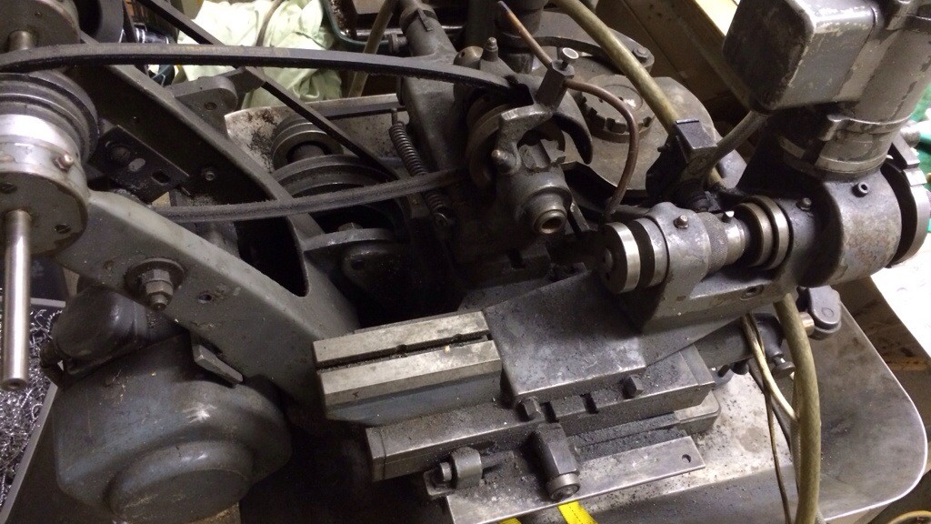
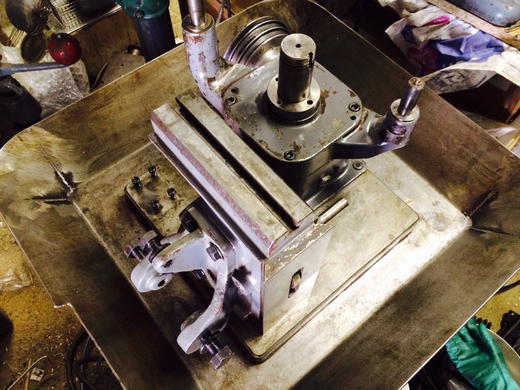
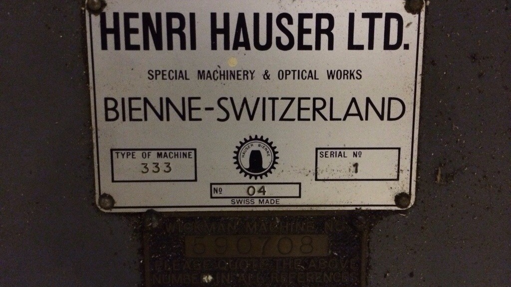
Having discovered that accurate centring of the cutter is critical when cutting pinions on the Aciera F1, I decided that it was time to set the Hauser 333 up as a dedicated pinion cutting machine. This would mean that the F1 was freed up for other jobs and that I would (hopefully) not have to go through the long process of centring a pinion cutter again.
The Hauser has power feed in 4 separate axes but for this first test I did not want it to move in Z (depth of cut) or Y (cutter centring). The belt driving the cams was turned by hand to get the axes at the extremes of travel.
The W12 centring scope was put into the workholding spindle and the cutter centred as accurately as I could, before clamping the gib strip tight. The position of the workpiece spindle would need adjusting later so that the cutter made the correct length of cut.
The centring scope was replaced by a collet holding a brass blank; brass was used for this and subsequent trials so that full depth cuts could be taken in a single pass.
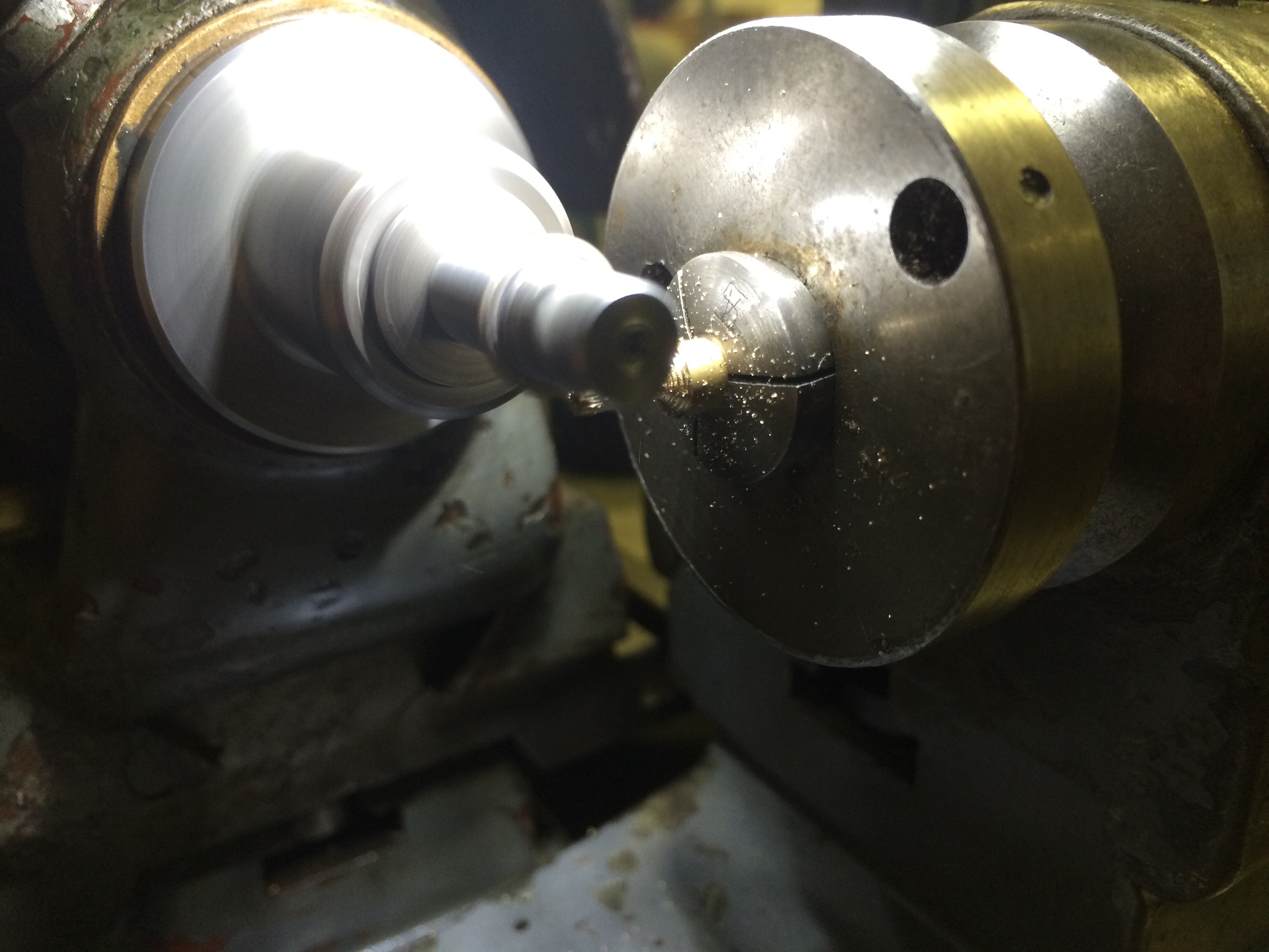
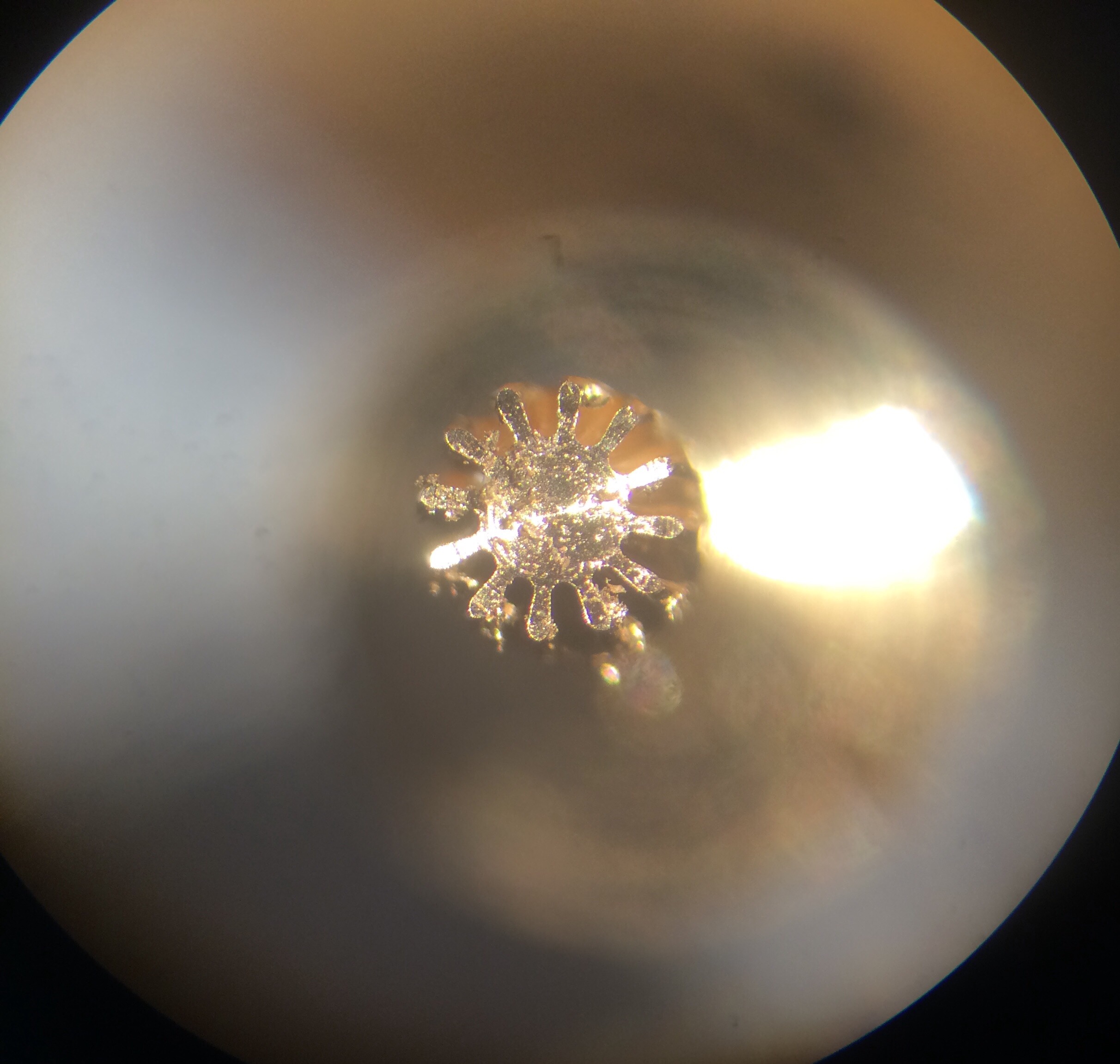
The result was very satisfying, with good centring of the cutter achieved after a few minor modifications of the cutter axis position.
Since the pinion blank was being prepared on the lathe and then transferred to the pinion cutter, I decided to set up for cutting between centres. This should help maintain concentricity of all the various operations. I also decided to start using the power feed on the cutter axis, so that the cutter moved out of the way after the teeth had been cut.
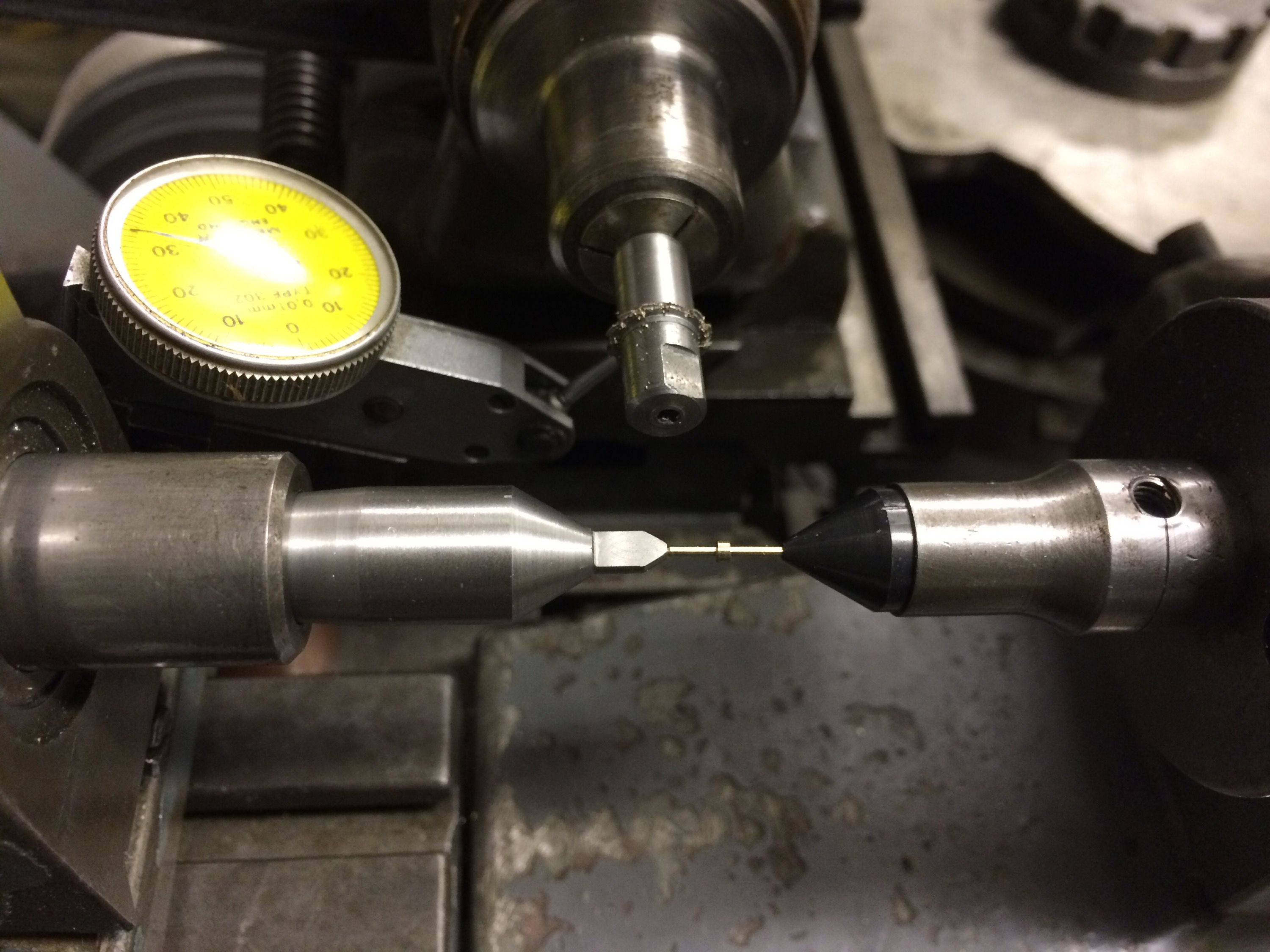
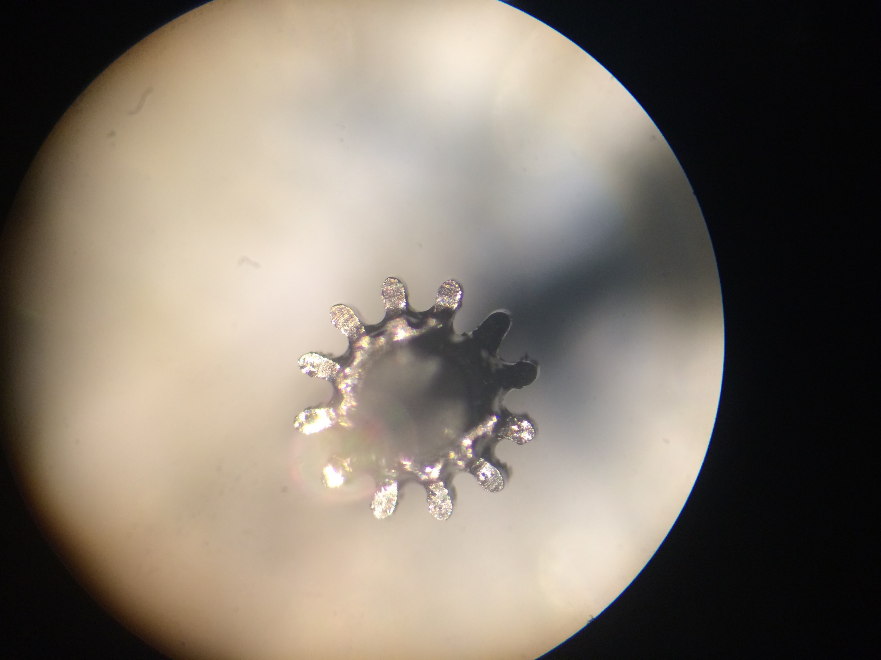
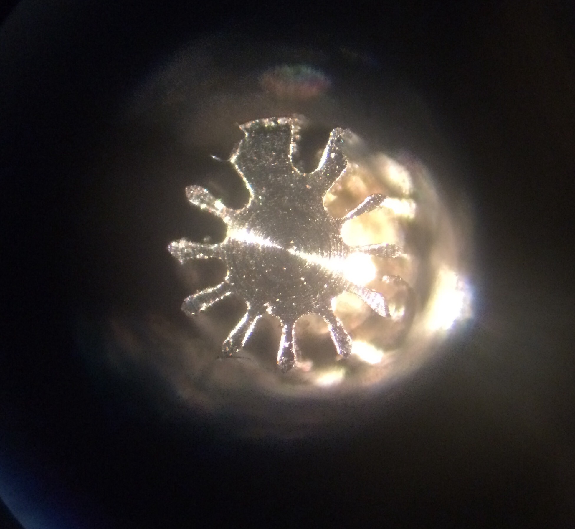
A few unsuccessful trials with uneven leaves led me to suspect that something was up with the alignment of the tailstock, the movement of the cutter axis, or even both:
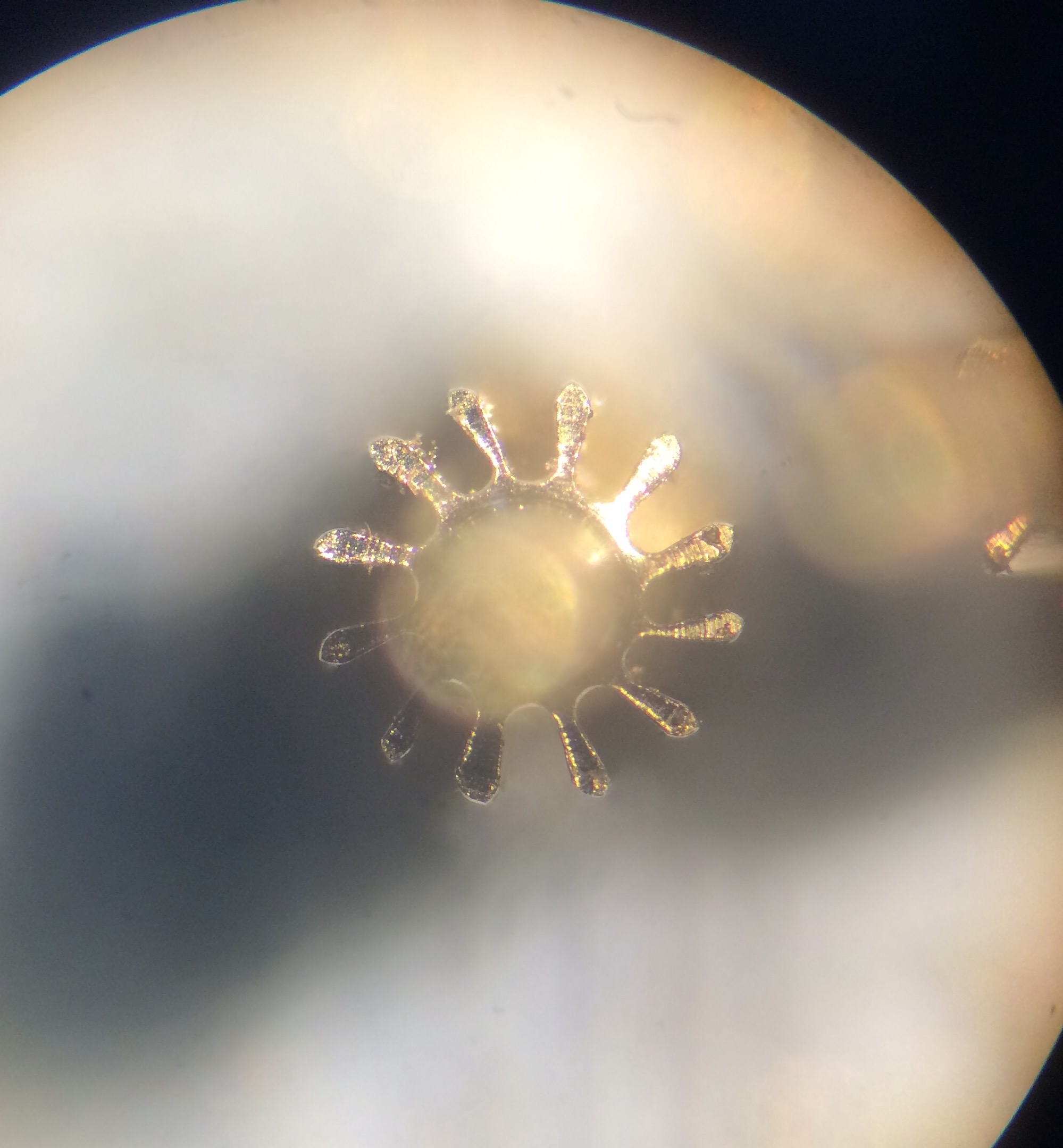
It didn’t take long to realise from a side view of the pinion that the tailstock was off centre, giving a helical pinion. What was harder to spot was the pattern in leaf irregularities; in the above photo every 4th leaf is much more deformed than its neighbours (see the leaf at about 11 o’clock). This could only mean one thing: the lobes in the driving cam were uneven.
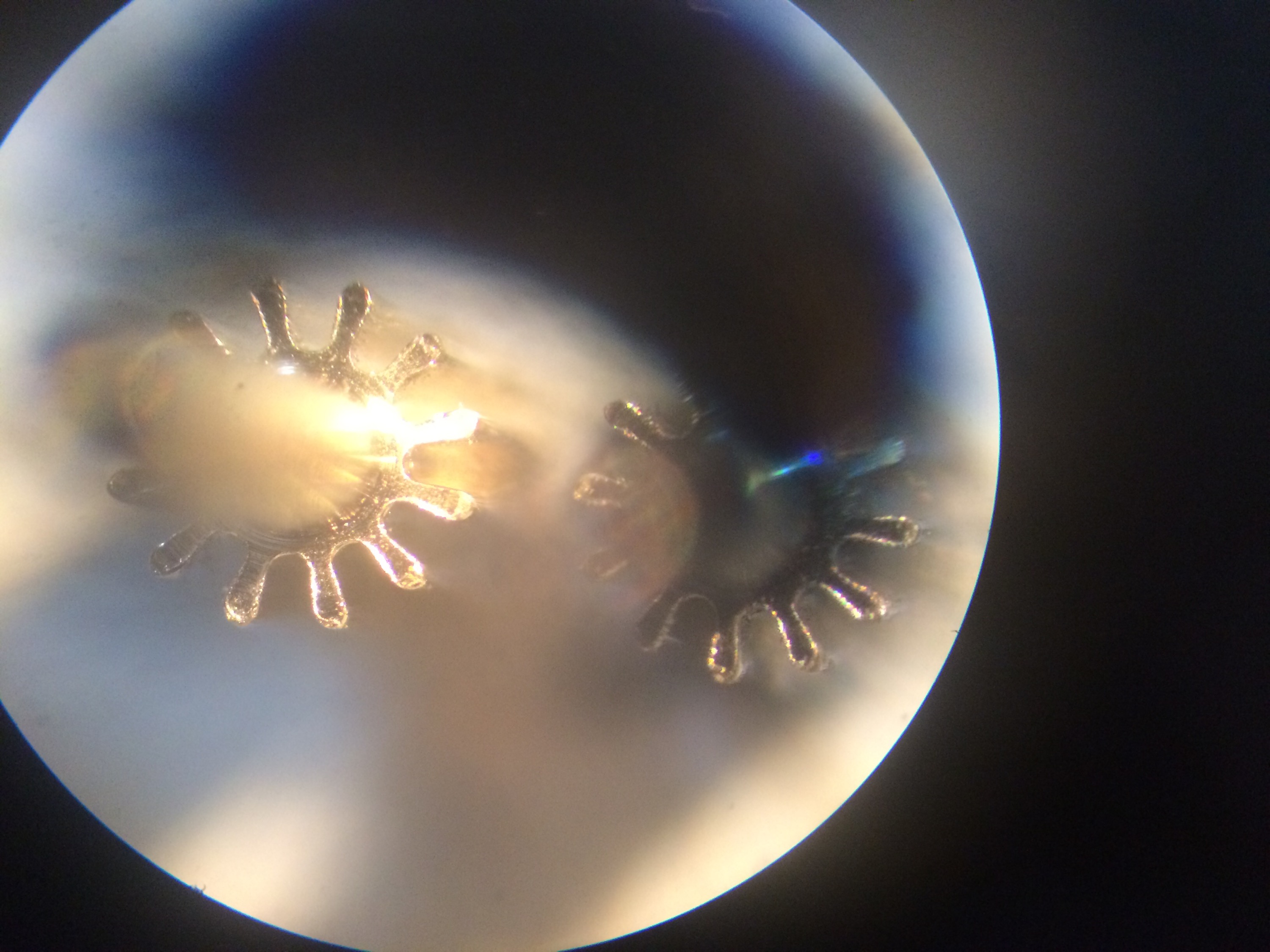
Once I established that the cam that drives the cutter axis forward has lobes of different heights and was therefore causing the cutter to be off-centre for 3 out of 4 the cuts, I decided to lock this axis once again. Again the workpiece was held in a collet and again it was simple to centre the cutter as the cutting progressed around a trial pinion; the final leaf cut appears at about 10 o’clock in the following photo:
The depth of cut is quite possibly not correct in this trial but since the blank wasn’t accurately turned to size this isn’t a fair test piece.
Next step was to get the tailstock centred and take some more test cuts between centres, still with the cutter axis locked. This did make extracting the pinion somewhat tricky but means I get accurate cuts, so this is a price worth paying until the uneven loves on the cam can be sorted.
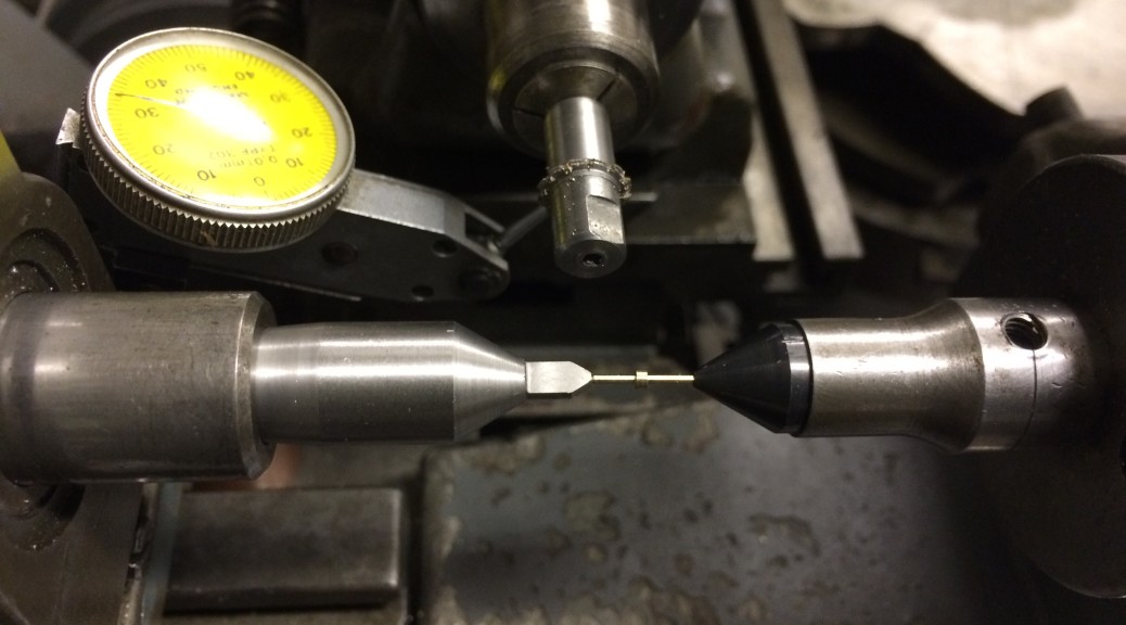
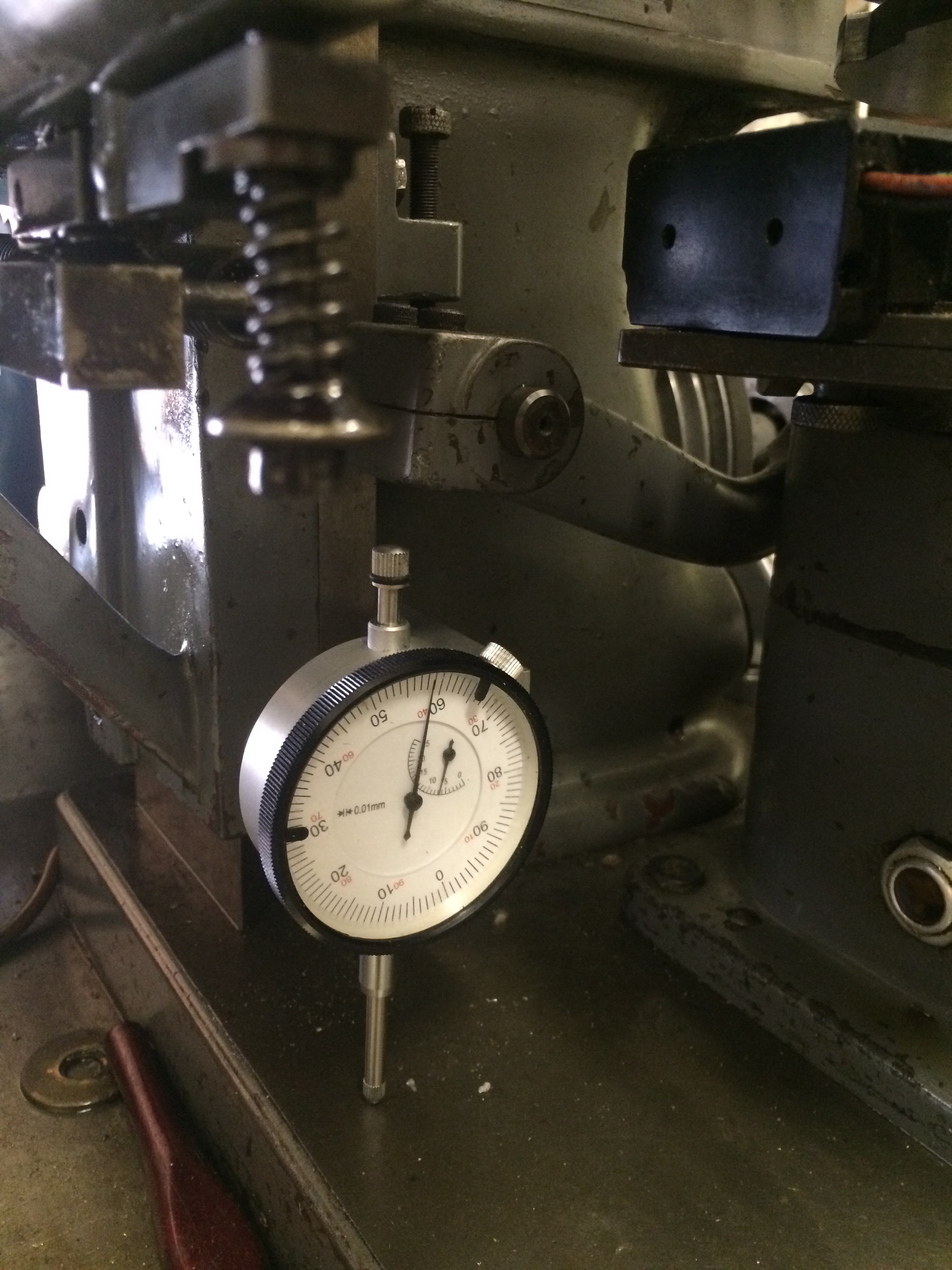
The tailstock was relatively far off centre to begin with and is still not quite there in the photo below, probably something like 0.01mm off. Adjustments were made with a dial indicator against the side of the centre so that the movement could be accurately measured.
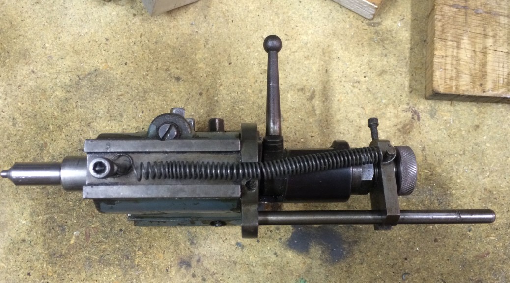
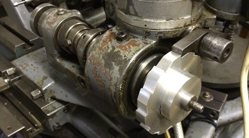
Before trying a steel pinion, which would need multiple cuts at measured depths, I decided to add better control of the Z axis. My first attempt was to replace the current fine pitch screw adjustment with a micrometer head. I made up a bracket to hold this but then struggled to get it actually attached to the machine because of limited clearance. In the process of doing this I moved the cutter axis to get it out of the way. Eventually I opted for using the original screw but adding a dial indicator so that I could at least measure the changes being made with the screw:
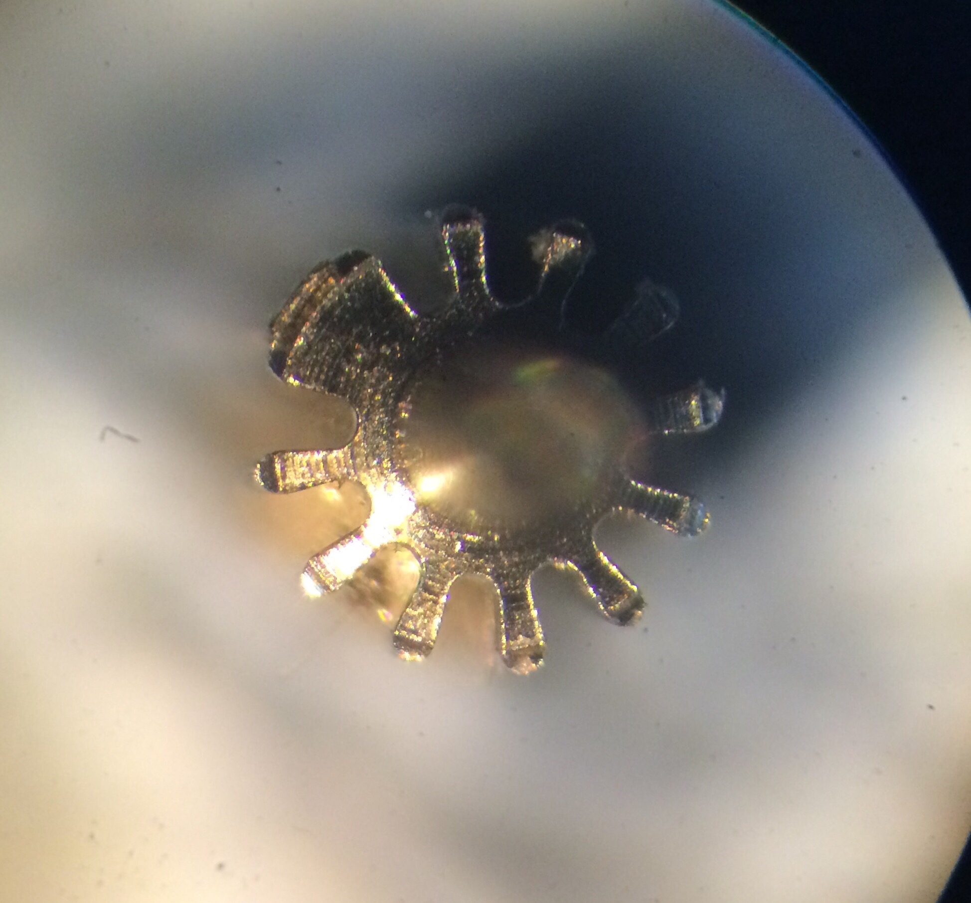
After realigning the cutter by eye, I made a test cut in brass. My guessed alignment turned out to be about 0.01mm off, so after a minor adjustment I had the machine ready to go. In the photo below the first cut is at 12 o’clock, continuing clockwise.
Then it was time to try cutting a steel pinion. The blank was prepared on the Schaublin 70 to fit between the centres, the depth of cut set at 0.1mm, the speed set to about 400rpm and the cutter and pinion blank covered in cutting fluid. Here it is after the third pass.
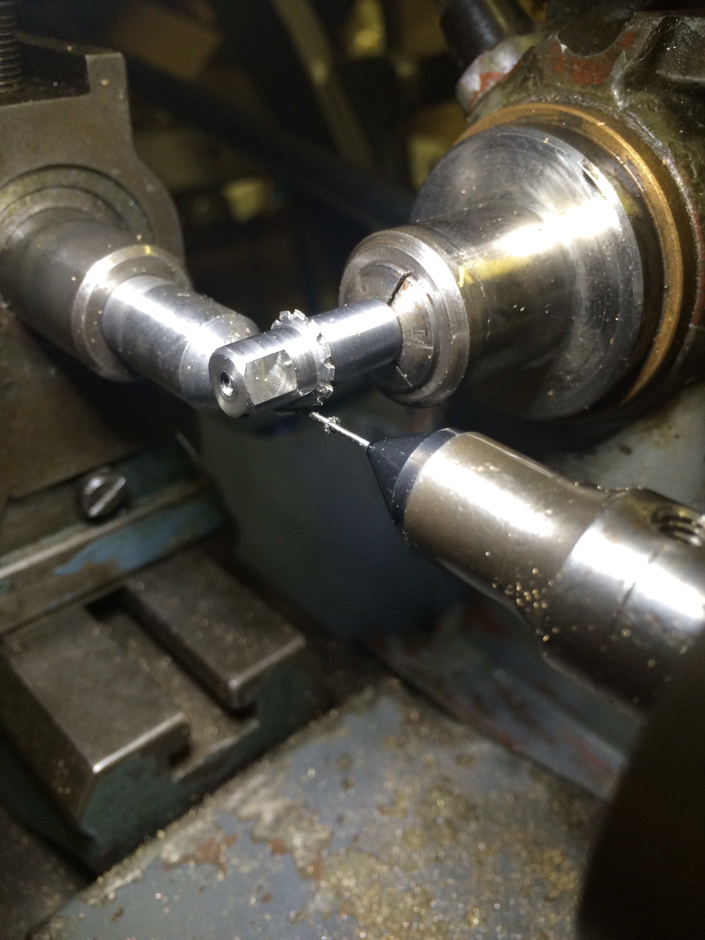
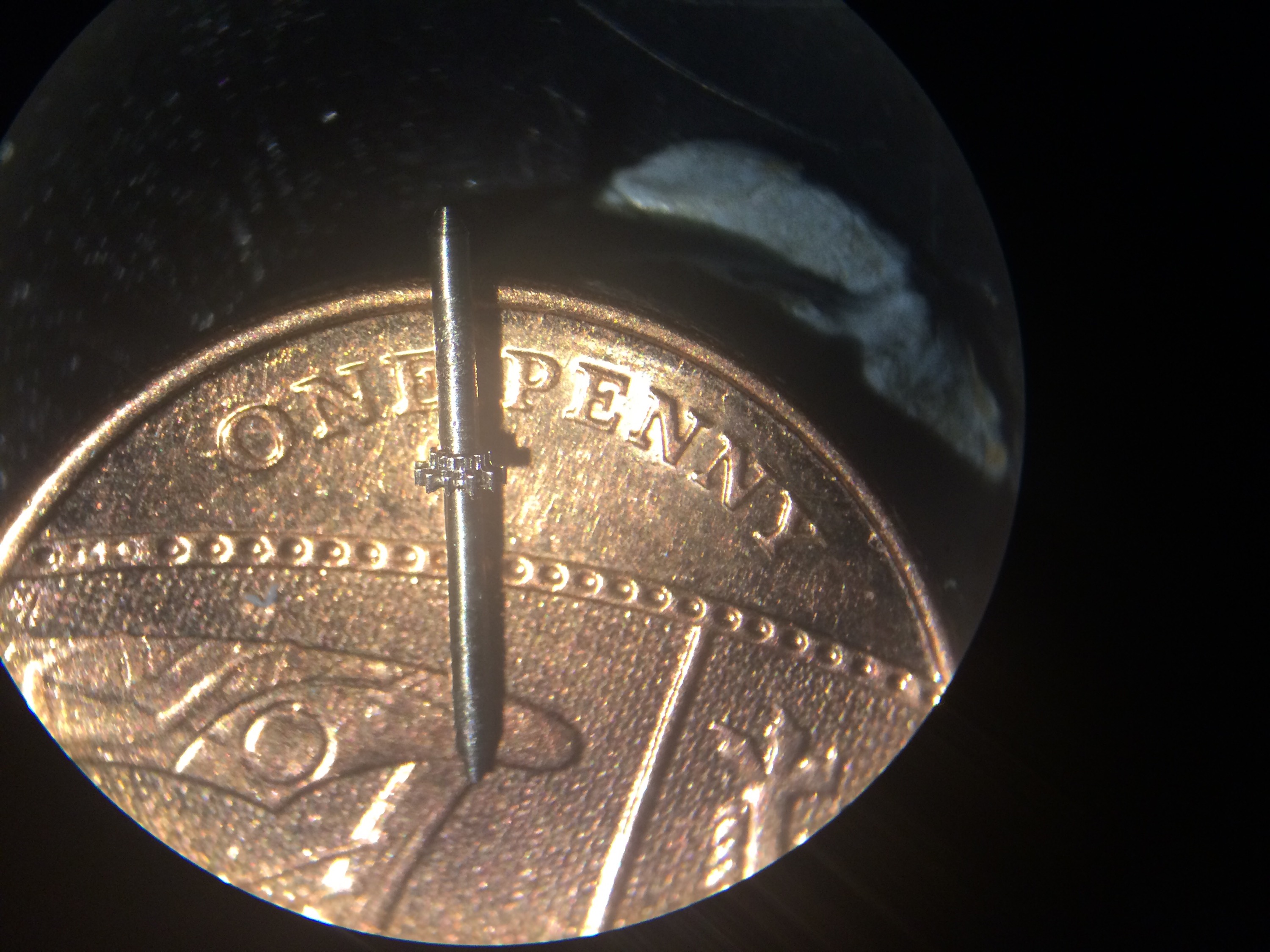
The result was very pleasing:
And sitting on a new penny for scale:
I now have a small USB powered pond pump that I plan to use for pumping a constant stream of cutting oil over the cutter when cutting steel. Ideally this would be powered from the Hauser itself so that it is only on when the spindle is powered, however adding this complexity this can wait.
Unfortunately the “I’ve done it” feeling was relatively short-lived… Once I’d made a few pinions for the 4th wheel I moved to making some for the 3rd wheel, which are a fair bit longer. This additional length made any offset between the tailstock and headstock much more apparent, resulting in helical teeth. To cut a relatively long story short, I eventually discovered that my female drive centre (described earlier in this post) had about 0.04mm runout, easily enough to totally mess up a 0.14 module pinion. I initially put this down to runout in the Hauser work holding spindle or the adapter that fits in the spindle to take W12 collets. However, after a period of about 2 months of inactivity in the workshop (but a fair bit of thinking about the problem), I took the centre and put in back in the Schaublin 70 to check whether the runout was an artefact of the centre or the Hauser and it was very obvious that the centre was at fault. Time for a new female drive centre.

