Category Archives: Machines

This page shows a few of the various machines in the workshop. Most of my machines are big and old and heavy. In my opinion old British or Swiss cast iron cannot be beaten in terms of rigidity, which in turn has a bearing on the accuracy that can be achieved. I have acquired the machines over a period of time, picking up job lots where possible in order to get the bits I want, then selling the remainder to other like-minded people.

There are mostly two sizes of each of the machines: big enough for ‘normal’ engineering, such as a lathe with 200mm swing; small for micro engineering, such as demanded by my watch project.

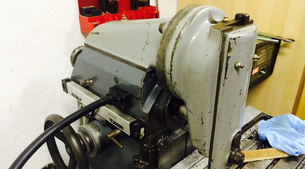
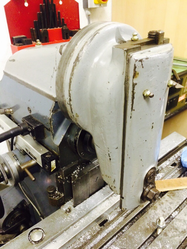
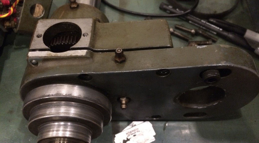
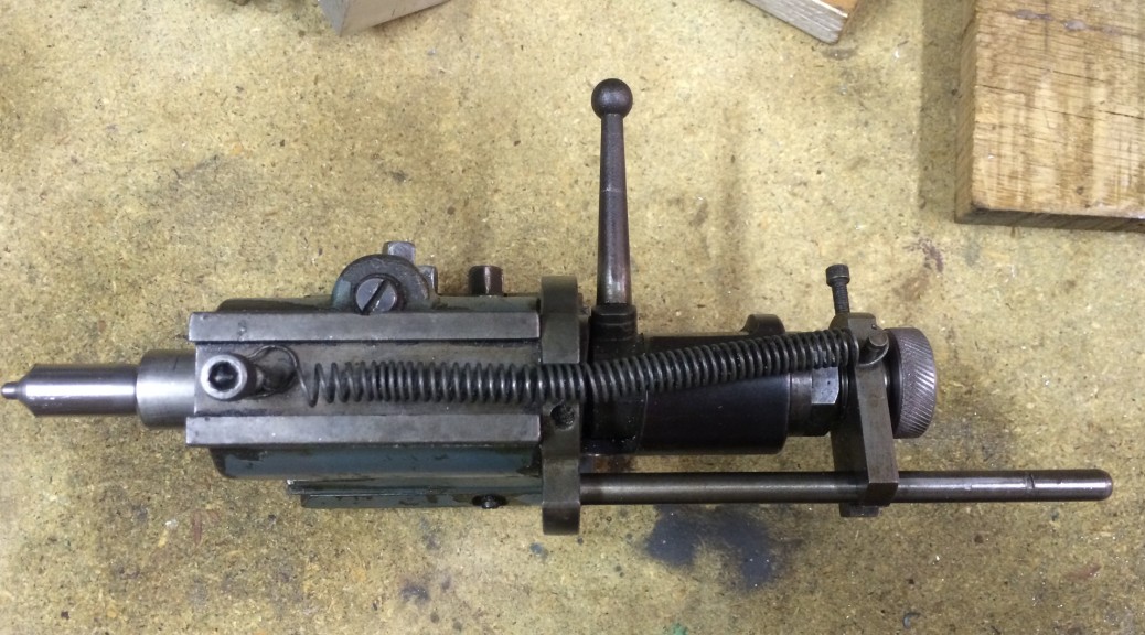
Slotting head tool holder

I’ve had the slotting head for the Aciera F3 for a few months but haven’t used it yet, mostly because I haven’t had any tooling or tool holders for it. Now I want to cut an internal key way to fix a wheel onto its shaft, so it was time to make some tooling. 

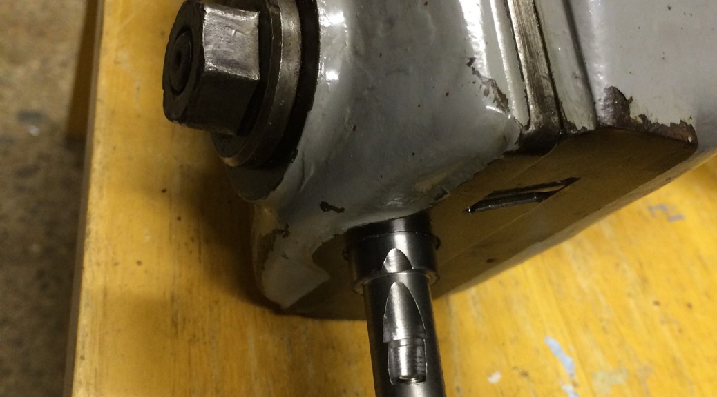
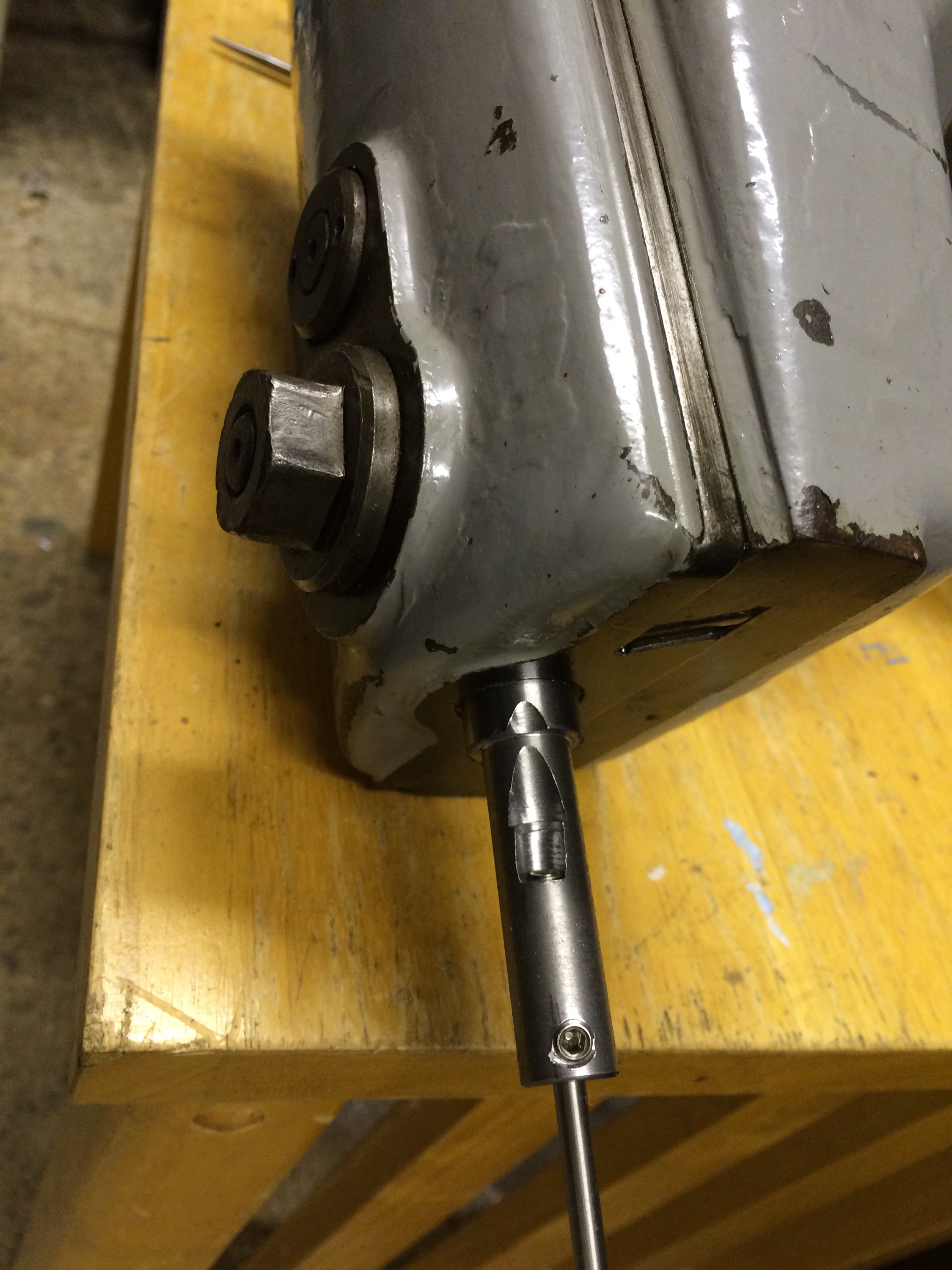
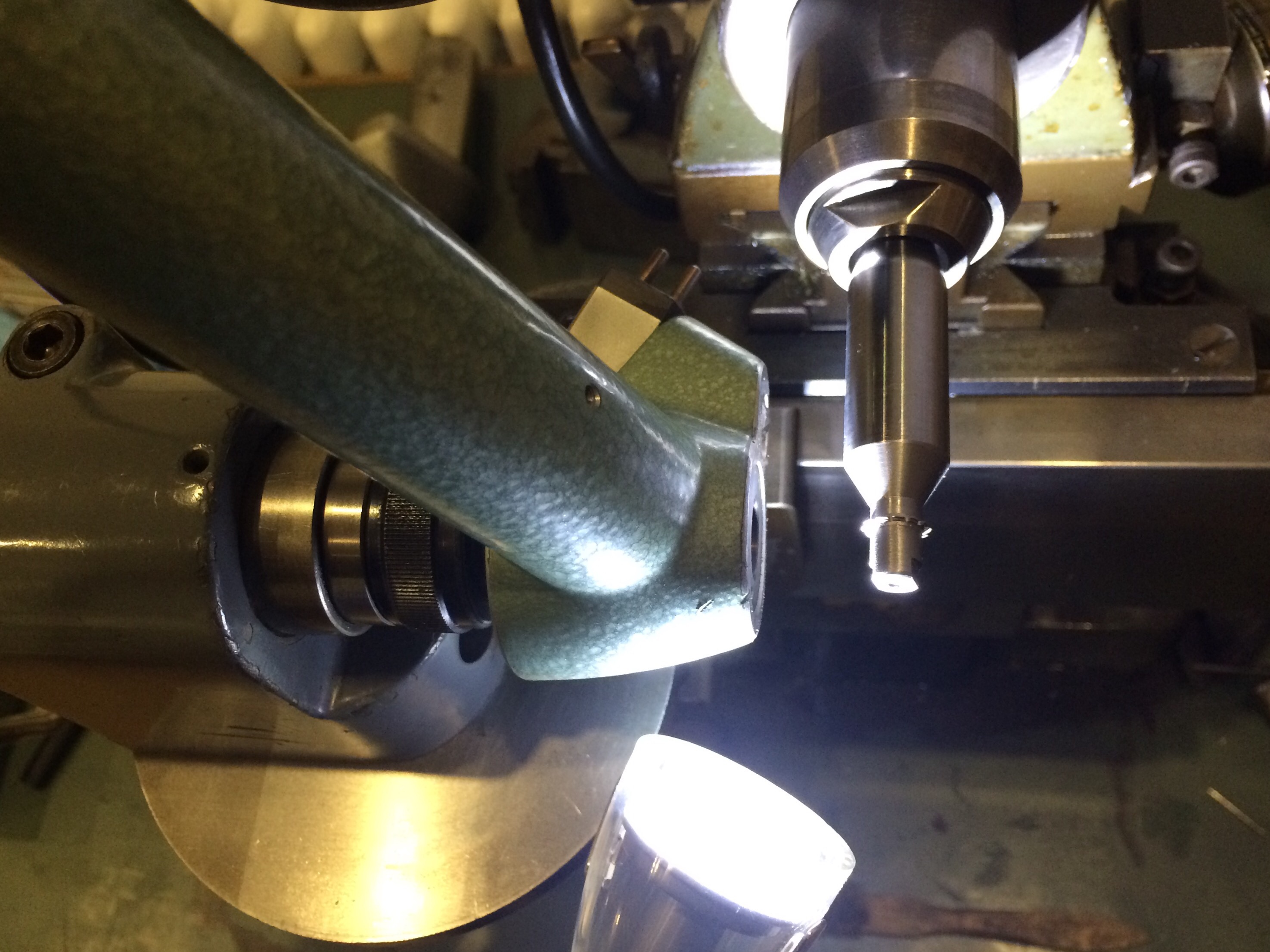
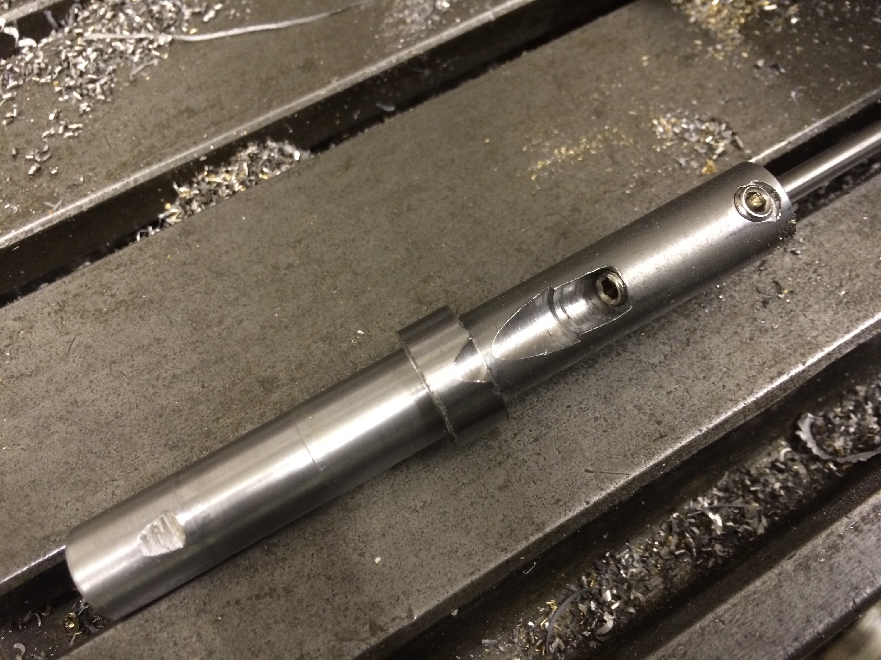
The slotting head has a 12mm hole for a tool holder but I didn’t have any 12mm diameter steel, so I started with a 16mm bar. The result is shown below. From left to right: parallel 12mm shank to fit in head; 16mm collar; top end of the 4mm slanting hole for the cutter, tapped for a 5mm grub screw so that the amount of protrusion of the cutter can be adjusted by pushing it out; head of 5mm grub screw for clamping the cutter (this does go below the surface when tight).

  
4mm diameter tool steel bar held in the holder, from which I shall grind or mill a cutter for a piece of 1/8″ square section key steel. 

 
It’s certainly not the neatest tooling I’ve ever made, not helped by the design of my dividing head (in which I’d planned to hold the piece on the mill while drilling the various holes) not allowing me to hold the piece in a collet, since the draw bar would foul the table [correction: I later discovered that the drawbar can be removed once the collet is secured, so I could have used the dividing head]. There was also insufficient clearance under the vertical head to allow me to use a chuck on the dividing head, so the piece was simply held in a vice and all angles set by eye. 


Pinion cutting on the Hauser 333

Having discovered that accurate centring of the cutter is critical when cutting pinions on the Aciera F1, I decided that it was time to set the Hauser 333 up as a dedicated pinion cutting machine. This would mean that the F1 was freed up for other jobs and that I would (hopefully) not have to go through the long process of centring a pinion cutter again. 

The Hauser has power feed in 4 separate axes but for this first test I did not want it to move in Z (depth of cut) or Y (cutter centring). The belt driving the cams was turned by hand to get the axes at the extremes of travel. 

The W12 centring scope was put into the workholding spindle and the cutter centred as accurately as I could, before clamping the gib strip tight. The position of the workpiece spindle would need adjusting later so that the cutter made the correct length of cut. 

The centring scope was replaced by a collet holding a brass blank; brass was used for this and subsequent trials so that full depth cuts could be taken in a single pass.
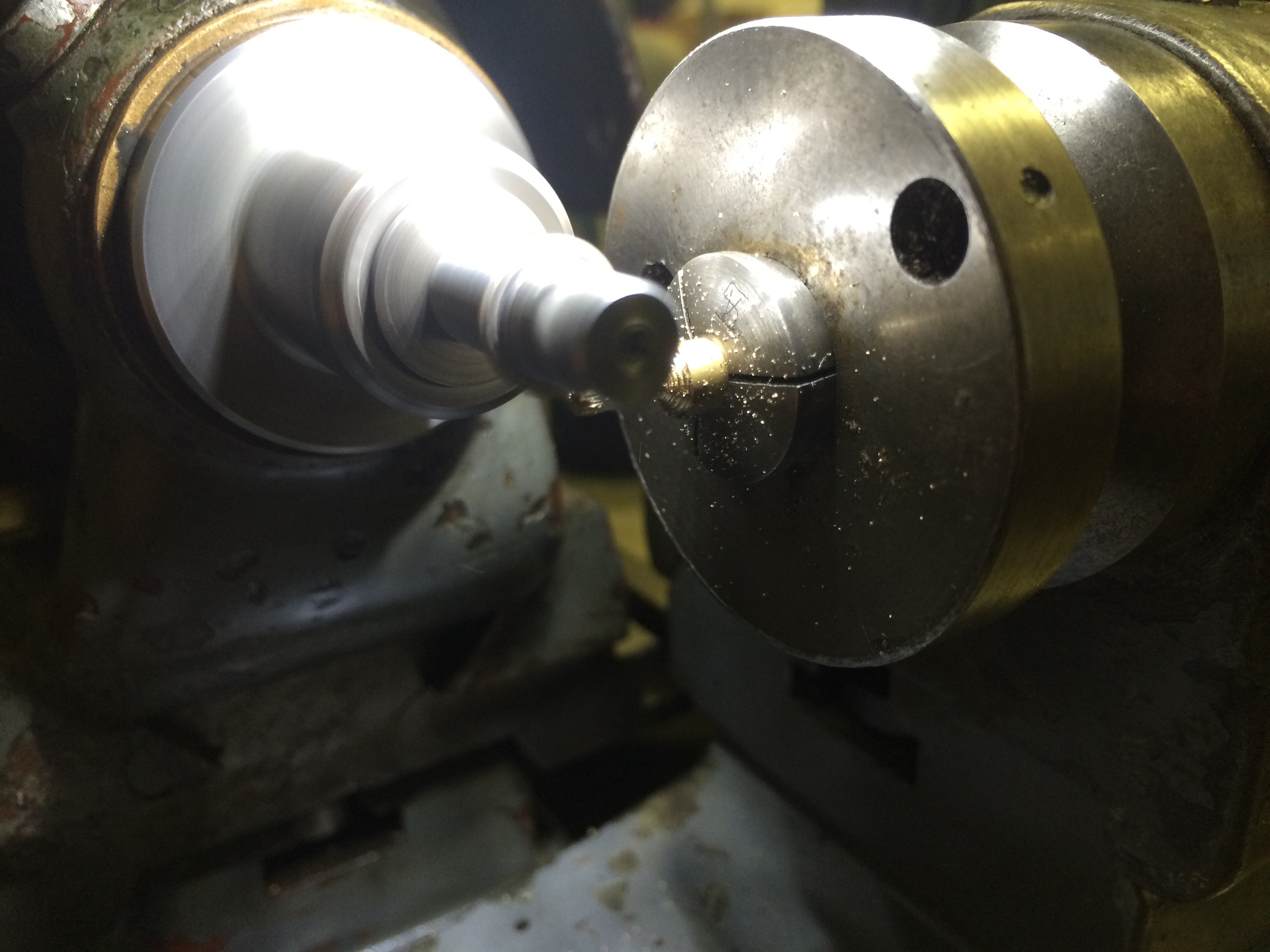
  

The result was very satisfying, with good centring of the cutter achieved after a few minor modifications of the cutter axis position. 
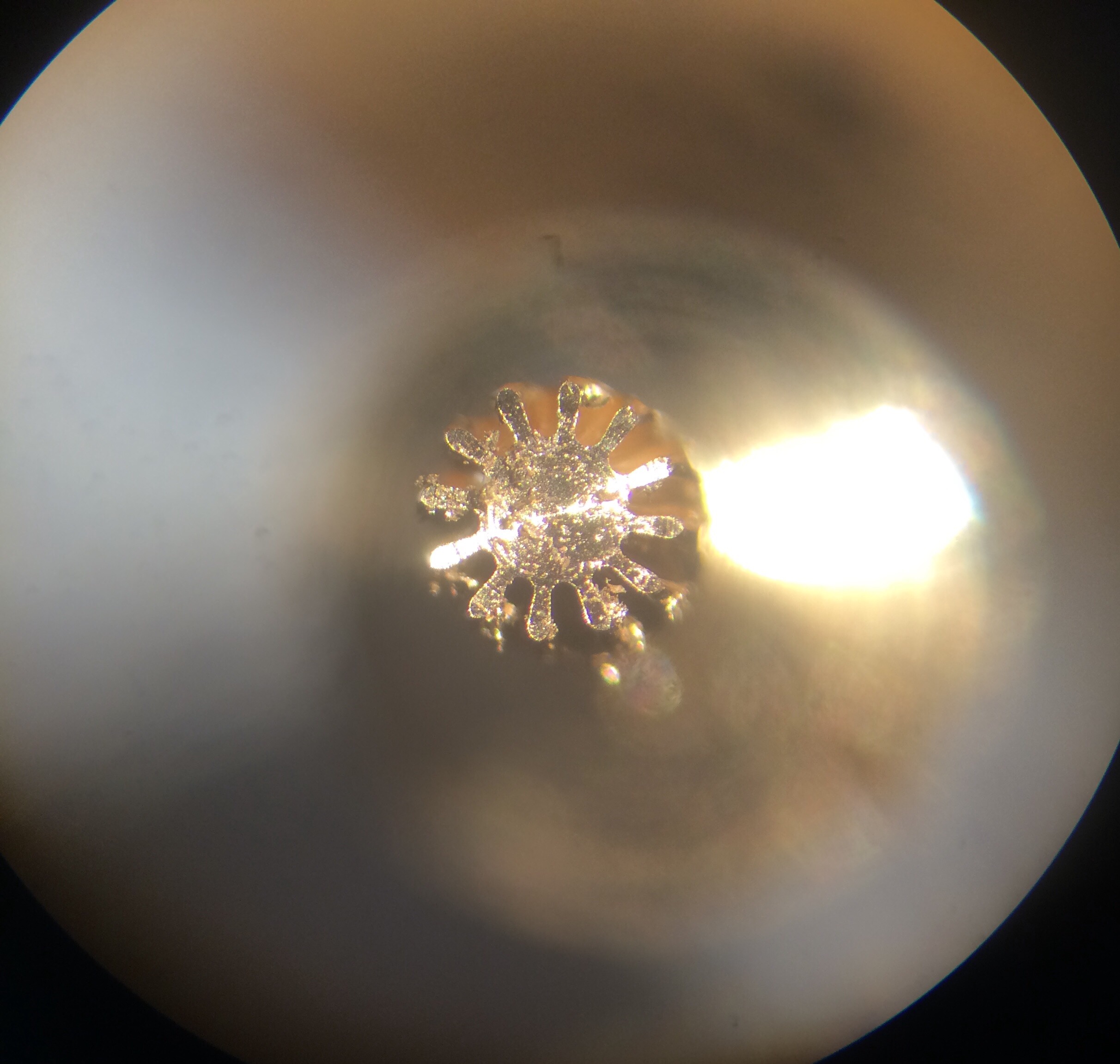
   

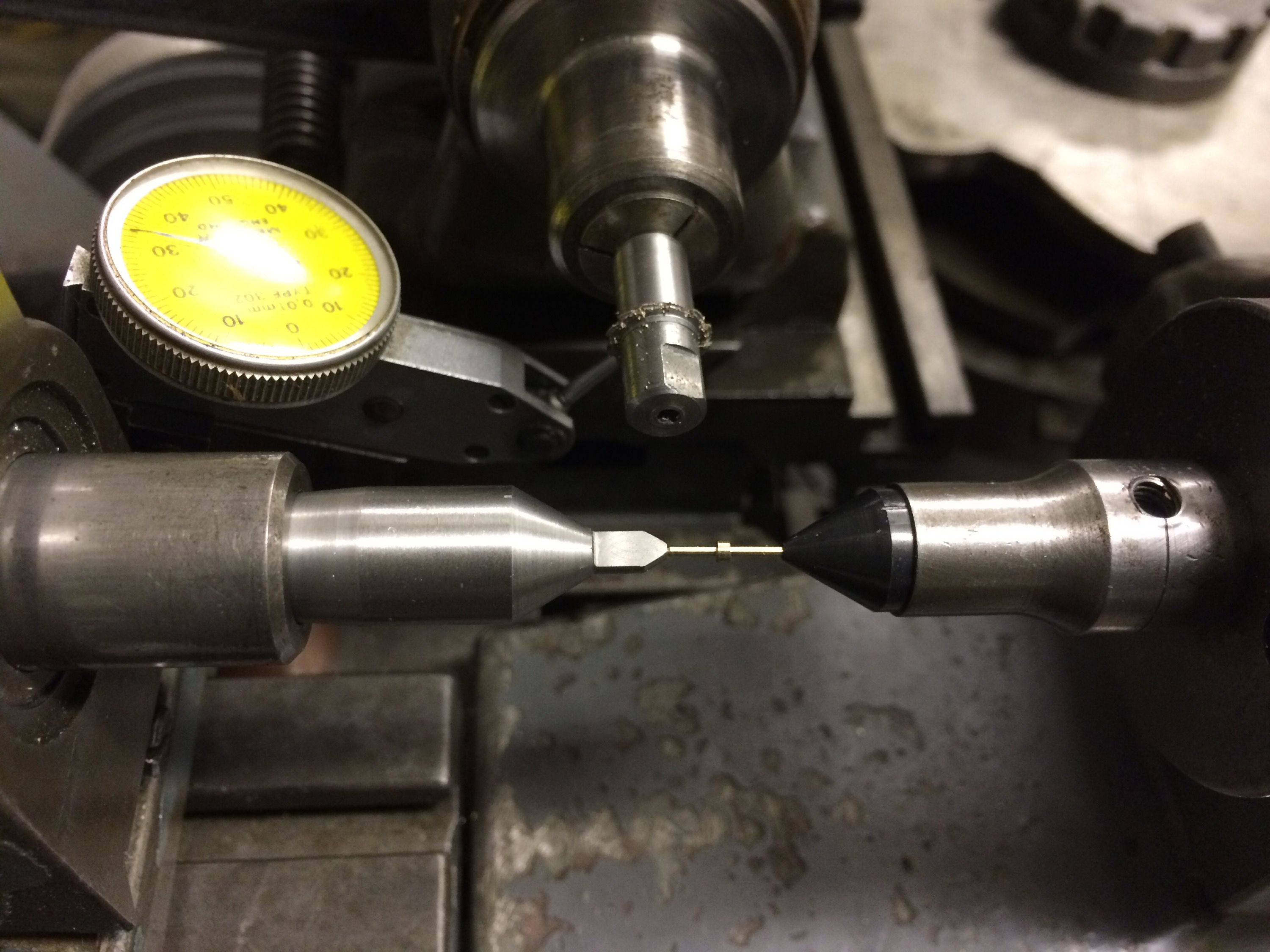
Since the pinion blank was being prepared on the lathe and then transferred to the pinion cutter, I decided to set up for cutting between centres. This should help maintain concentricity of all the various operations. I also decided to start using the power feed on the cutter axis, so that the cutter moved out of the way after the teeth had been cut. 
A few unsuccessful trials with uneven leaves led me to suspect that something was up with the alignment of the tailstock, the movement of the cutter axis, or even both:
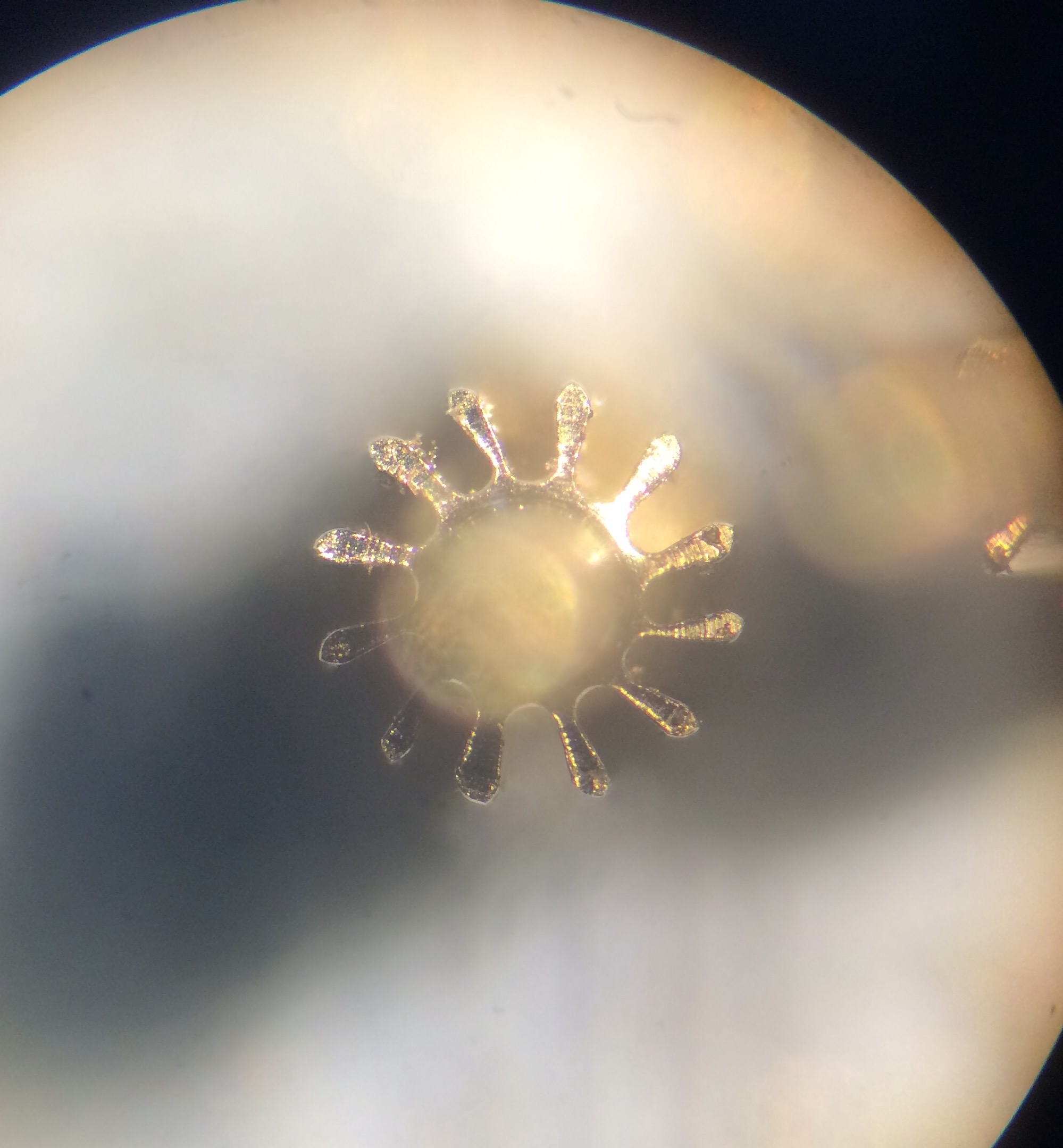
 

It didn’t take long to realise from a side view of the pinion that the tailstock was off centre, giving a helical pinion. What was harder to spot was the pattern in leaf irregularities; in the above photo every 4th leaf is much more deformed than its neighbours (see the leaf at about 11 o’clock). This could only mean one thing: the lobes in the driving cam were uneven. 
Once I established that the cam that drives the cutter axis forward has lobes of different heights and was therefore causing the cutter to be off-centre for 3 out of 4 the cuts, I decided to lock this axis once again. Again the workpiece was held in a collet and again it was simple to centre the cutter as the cutting progressed around a trial pinion; the final leaf cut appears at about 10 o’clock in the following photo:
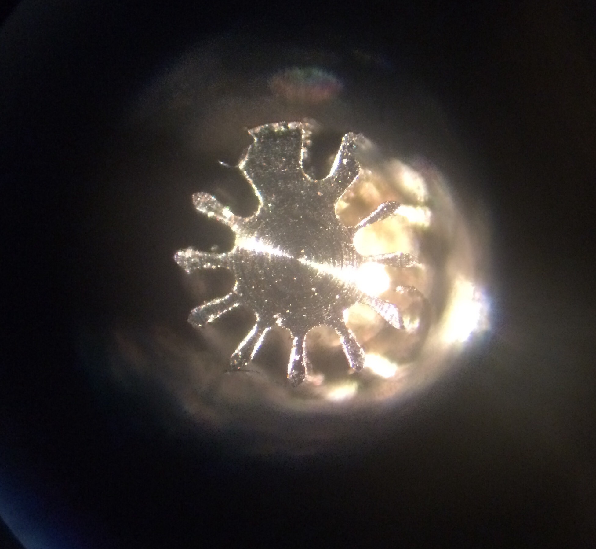
 

The depth of cut is quite possibly not correct in this trial but since the blank wasn’t accurately turned to size this isn’t a fair test piece. 
Next step was to get the tailstock centred and take some more test cuts between centres, still with the cutter axis locked. This did make extracting the pinion somewhat tricky but means I get accurate cuts, so this is a price worth paying until the uneven loves on the cam can be sorted. 

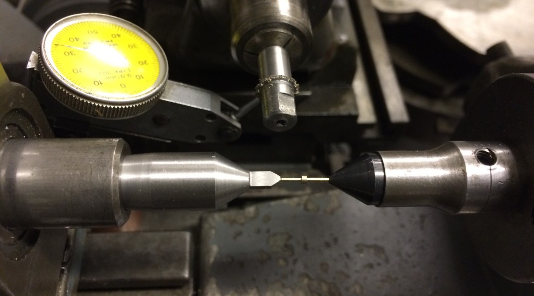
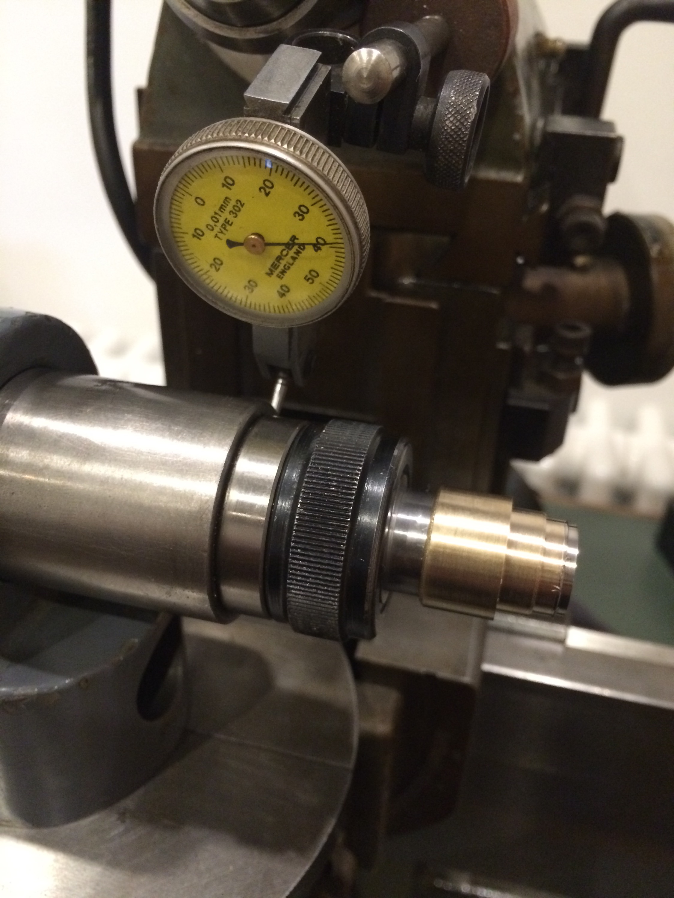
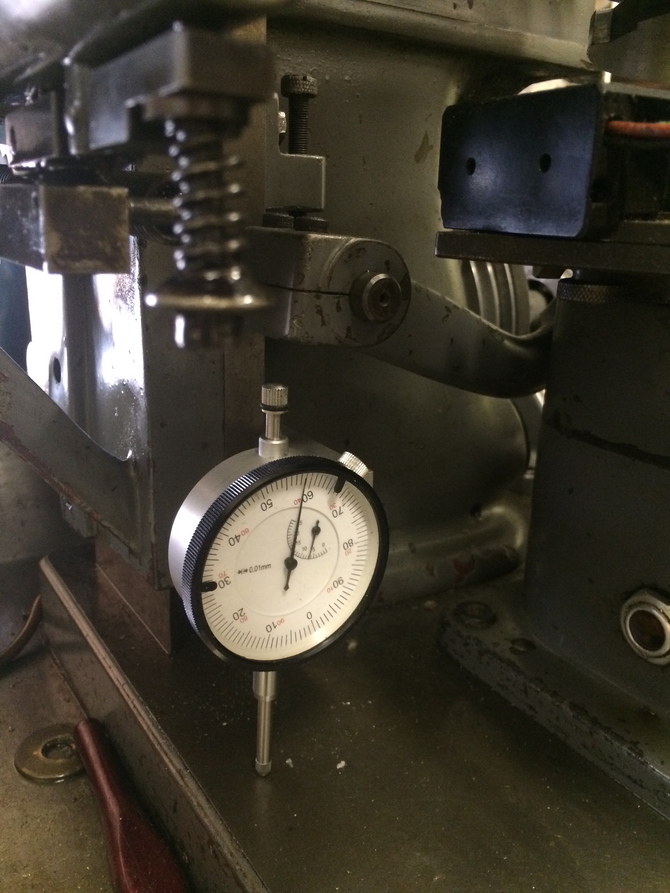
The tailstock was relatively far off centre to begin with and is still not quite there in the photo below, probably something like 0.01mm off. Adjustments were made with a dial indicator against the side of the centre so that the movement could be accurately measured. 
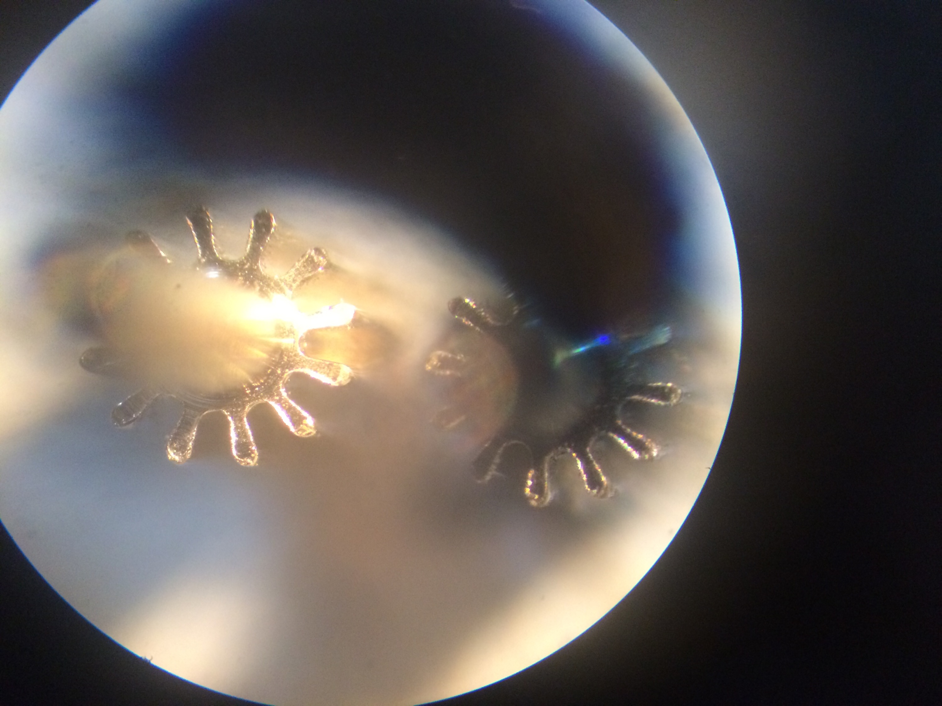
  

Before trying a steel pinion, which would need multiple cuts at measured depths, I decided to add better control of the Z axis. My first attempt was to replace the current fine pitch screw adjustment with a micrometer head. I made up a bracket to hold this but then struggled to get it actually attached to the machine because of limited clearance. In the process of doing this I moved the cutter axis to get it out of the way. Eventually I opted for using the original screw but adding a dial indicator so that I could at least measure the changes being made with the screw:
 

After realigning the cutter by eye, I made a test cut in brass. My guessed alignment turned out to be about 0.01mm off, so after a minor adjustment I had the machine ready to go. In the photo below the first cut is at 12 o’clock, continuing clockwise. 
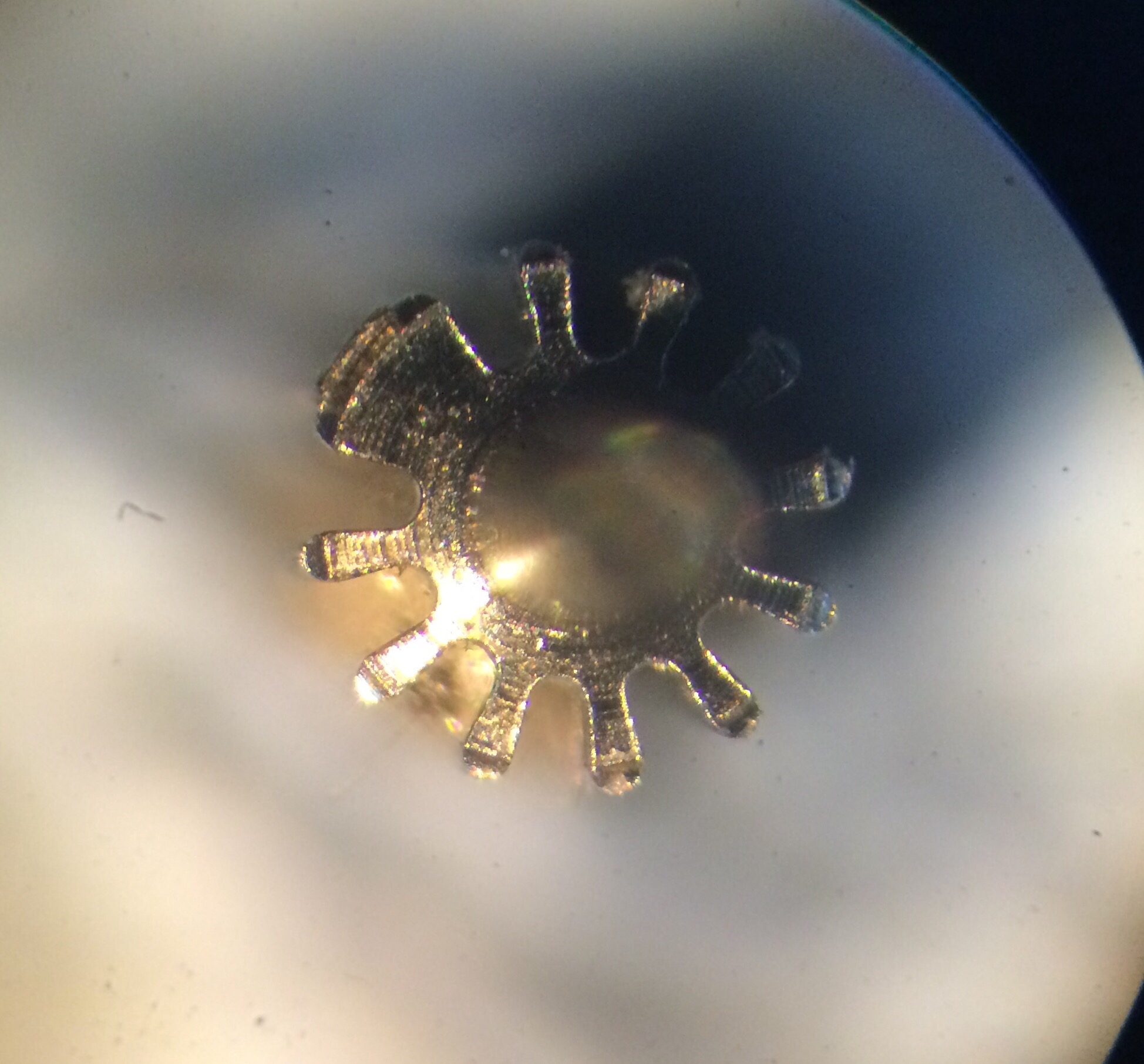
 

Then it was time to try cutting a steel pinion. The blank was prepared on the Schaublin 70 to fit between the centres, the depth of cut set at 0.1mm, the speed set to about 400rpm and the cutter and pinion blank covered in cutting fluid. Here it is after the third pass.   
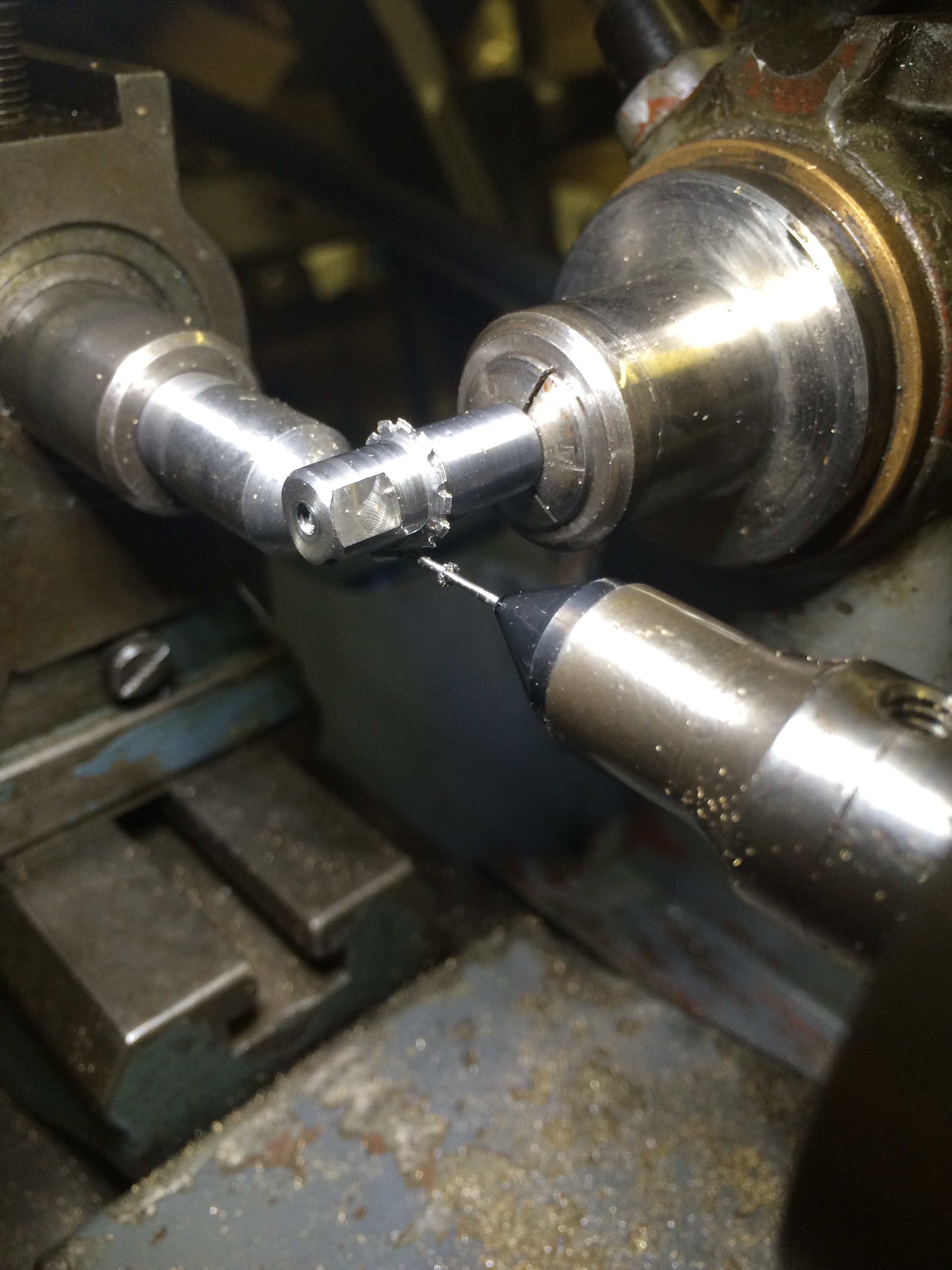
 

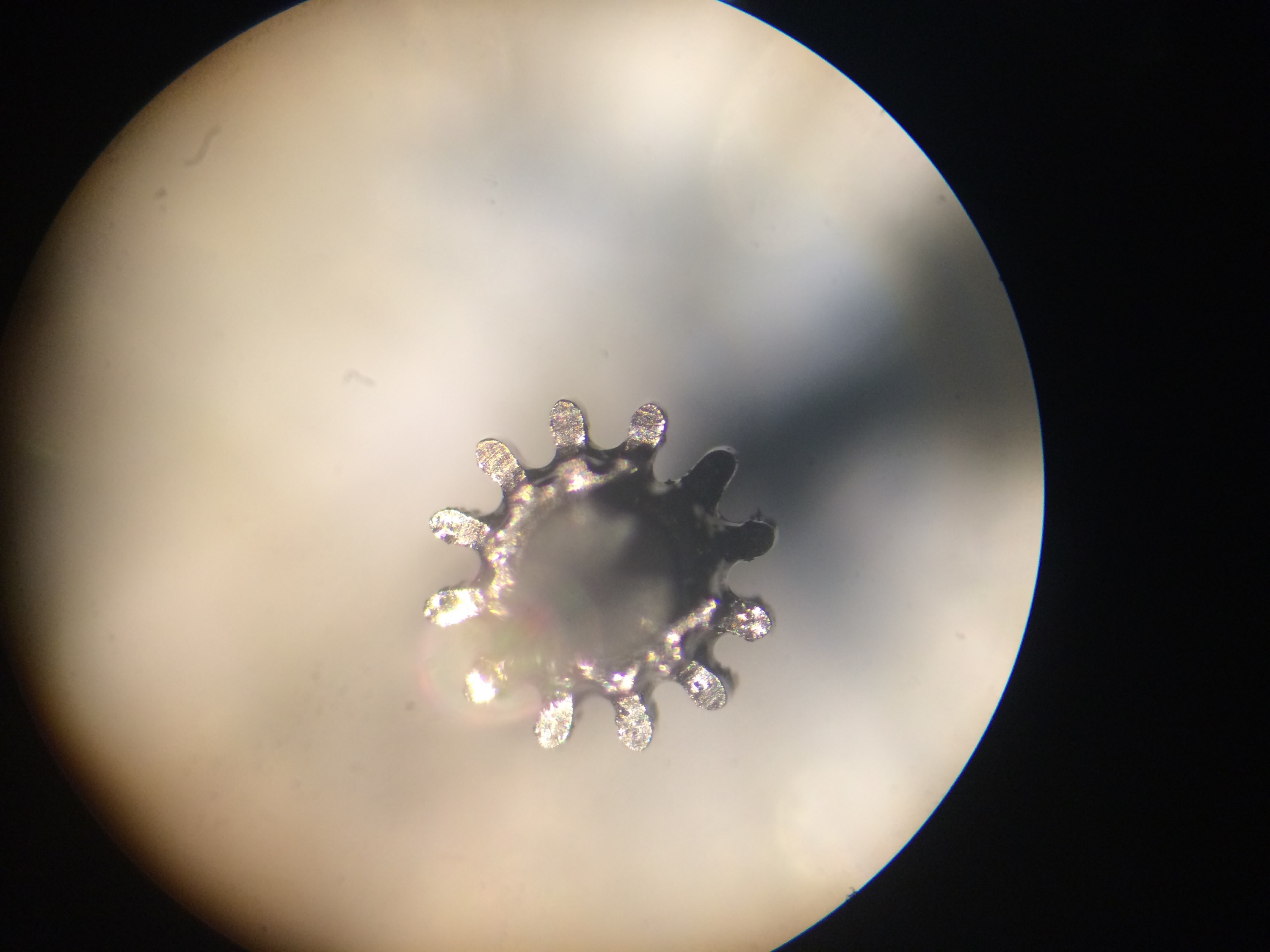
The result was very pleasing:


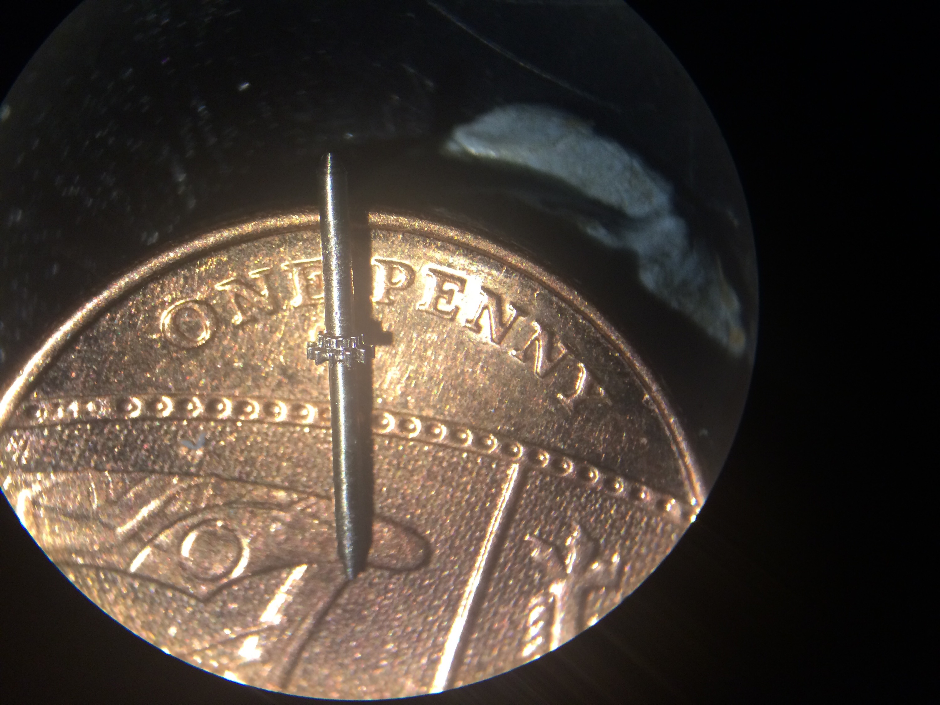
And sitting on a new penny for scale:
  

I now have a small USB powered pond pump that I plan to use for pumping a constant stream of cutting oil over the cutter when cutting steel. Ideally this would be powered from the Hauser itself so that it is only on when the spindle is powered, however adding this complexity this can wait. 

Unfortunately the “I’ve done it” feeling was relatively short-lived… Once I’d made a few pinions for the 4th wheel I moved to making some for the 3rd wheel, which are a fair bit longer. This additional length made any offset between the tailstock and headstock much more apparent, resulting in helical teeth. To cut a relatively long story short, I eventually discovered that my female drive centre (described earlier in this post) had about 0.04mm runout, easily enough to totally mess up a 0.14 module pinion. I initially put this down to runout in the Hauser work holding spindle or the adapter that fits in the spindle to take W12 collets. However, after a period of about 2 months of inactivity in the workshop (but a fair bit of thinking about the problem), I took the centre and put in back in the Schaublin 70 to check whether the runout was an artefact of the centre or the Hauser and it was very obvious that the centre was at fault. Time for a new female drive centre. 
Aligning the centring microscope

I had been having problems when trying to cut pinions, ending up with misshapen leaves as if the cutter was off centre. The centring scope had been used to centre the cutter each time so this was suspect number one. 
A quick search on the web for the maker of my scope, Aubert, revealed they were still in business. They even provide instructions for their current scopes on their website (http://www.marcel-aubert-sa.ch/produkte/anleitung/anl_pdf/anl_mik/m02_mik_111_118.pdf). 

Initial inspection of my scope failed to find the four adjustment screws, Continue reading Aligning the centring microscope

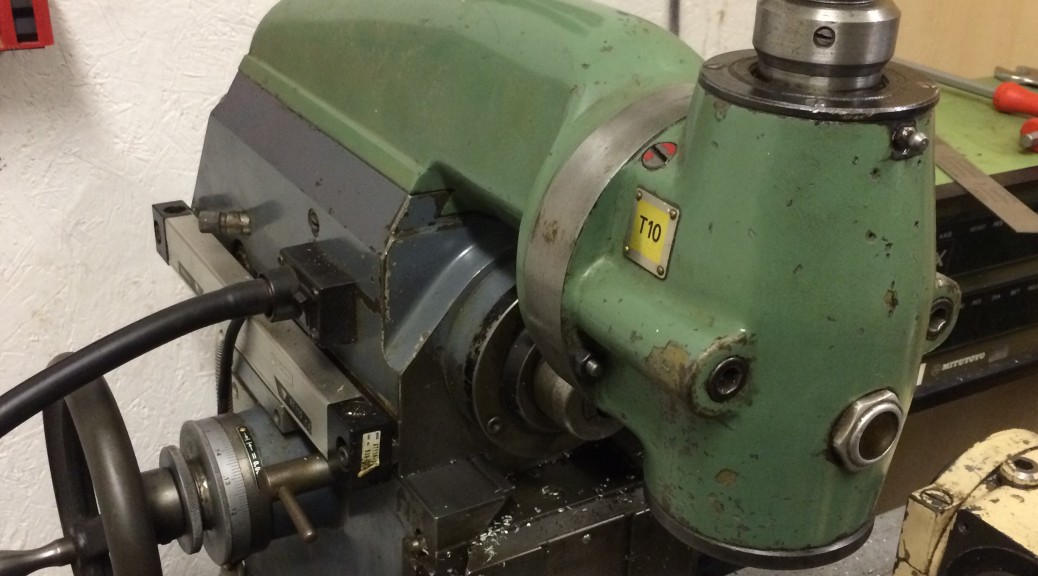
Aciera F3 vertical head

When I bought the F3 it came with a just the high speed vertical head. While this has been very useful so far, its speed range of 1000-6000 rpm suggests that it is best suited to small cutters and probably not the right thing to use for milling large pockets or hard materials (1000 rpm is just about ok for an 8mm carbide end mill in steel). My searching for a vertical head was finally rewarded (even though it’s not the Continue reading Aciera F3 vertical head

Spindle problems with the Aciera F1

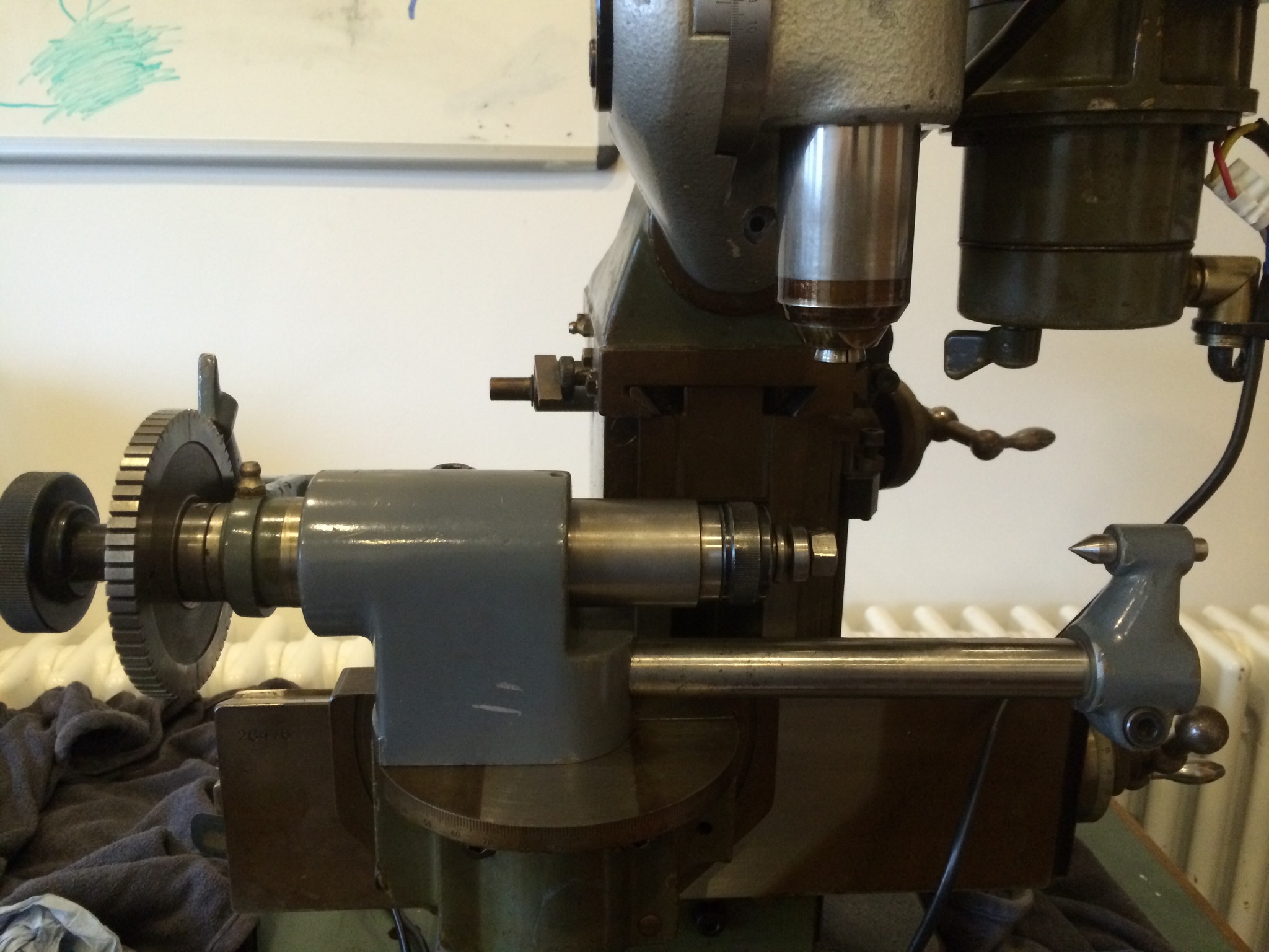
The faff to get everything set up for wheel cutting seemed endless: even after fitting up the electronic indexing head to the spindle I made a W12 wax chuck, then machined a blank arbour to take the cutter and made a nut to clamp the cutter in place. I used a dial indicator to set the indexing spindle perpendicular to the cutter axis:

(null)

Then put the centring microscope in the indexing spindle in order to get the cutter dead centre:

(null)

It was at Continue reading Spindle problems with the Aciera F1

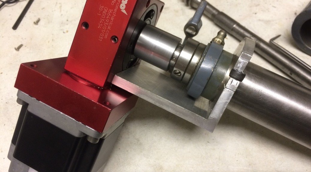
Worm drive for wheel cutting on the Aciera F1

At last, more progress on the tool making. After breaking the cutting tool while making the hob for the worm wheel, I started looking around for off-the-shelf worm drives. A low backlash one came up on eBay for $100 including a stepper motor, so I jumped.

My original plan with the bought drive was to bore out the centre of the worm wheel so that it would fit on the spindle of the direct dividing head (or indexing head) of the Continue reading Worm drive for wheel cutting on the Aciera F1

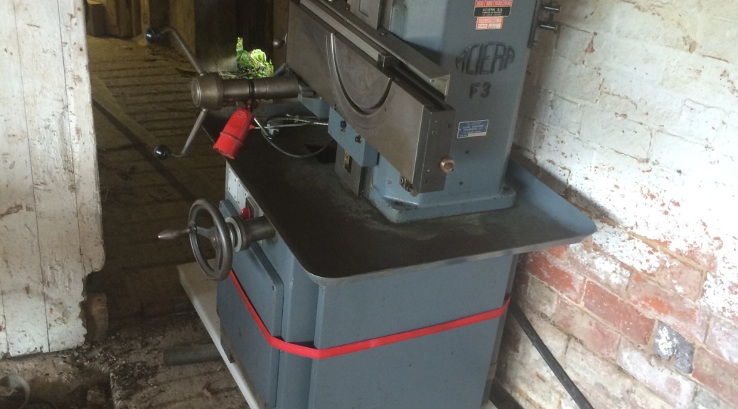
Moving the Aciera F3 into the workshop

One thing is for sure – while the F3 isn’t that big, it is certainly solidly built. Having learned from the effort involved to get the 750kg of Hardinge lathe up the slight incline into the workshop, the F3 was slid onto a length of kitchen worktop with short lengths of scaffold pole underneath as rollers.
IMG_5018-0.JPG

One end of a ratchet strap was looped around the bottom of the base, with the ratchet itself attached to a strong anchor inside the Continue reading Moving the Aciera F3 into the workshop

An Aciera F1

The Aciera F1 is considered by some to be the perfect partner for the Schaublin 70 lathe in the watchmaker’s workshop. Rightly so in my opinion: it takes the same W12 collets as the Schaublin 70, has the same thread on the nose of the indexing spindle and can easily be set up for either precision vertical milling or wheel cutting.
IMG_4996.JPG

I have just got hold of a nice example of one, albeit in need of a clean. It came with Continue reading An Aciera F1

Changes to the workshop – the Aciera F3

Having been keeping my eyes open for a nice Aciera F3, I finally found one
this week. For a change, it was only 40 minutes drive away (most of my machines have involved round trips of around 6 hours or more).

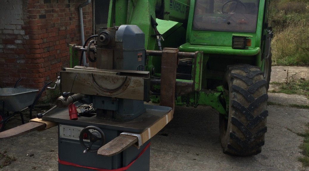
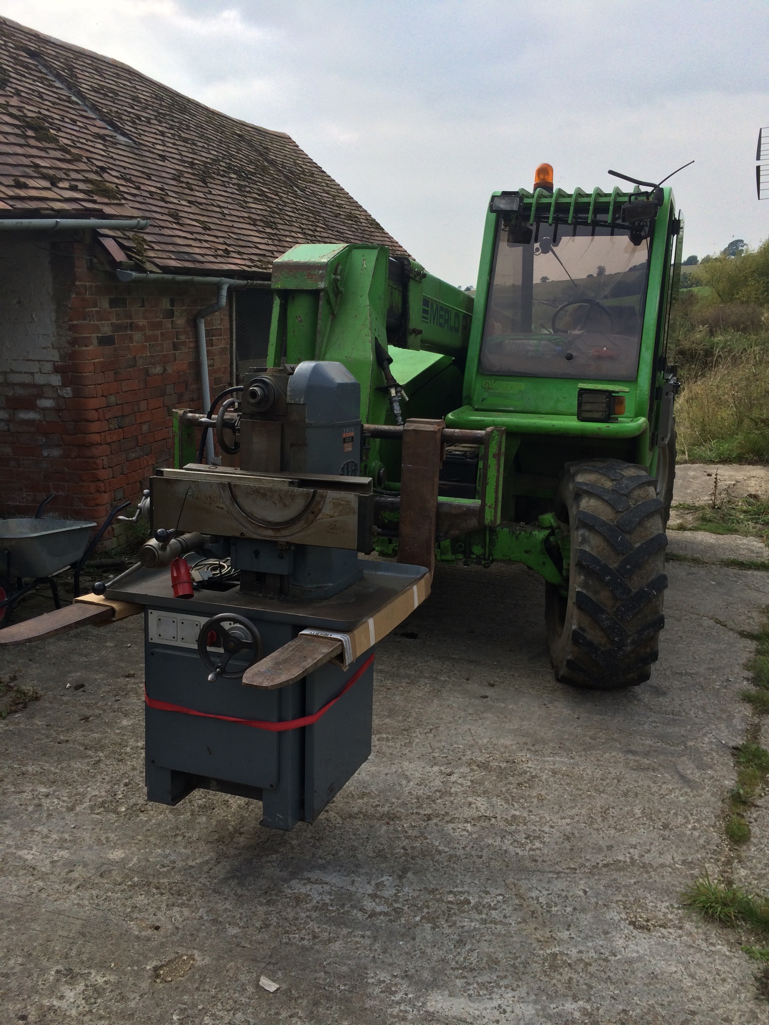
Collection was simple, unloading at the workshop wasn’t that much more complicated. With the aid of a borrowed telehandler, it was lifted off the trailer and posted under a shed ready for moving into the workshop.
IMG_4920.JPG

The next step is to clear space Continue reading Changes to the workshop – the Aciera F3

New cam disks for the Hauser

A quick trip to the local scrap yard got me a piece of 6mm steel plate large enough to make at least two new cam disks for the Hauser. These have been roughed into octagons using an angle grinder, ready to either put on the lathe or a rotary table on the mill.

I still haven’t worked out how to hold them while machining them round. Ultimately they need a 60mm hole through the middle for mounting on the post of the Continue reading New cam disks for the Hauser

Tailstock centre for the Hauser 333

The Hauser came with a tailstock (adjustable in both height and Y position) but with no centre. I had tried various centres in it, including those with small Morse tapers and the Schaublin 2 degree taper, but none fitted. Time to make my own.

I’m sure there must be a good way to copy an internal taper but I opted for trial and error. My Hardinge lathe has a taper-turning attachment that makes it easy to adjust the angle of the taper Continue reading Tailstock centre for the Hauser 333

New ratchet wheel for the Hauser 333

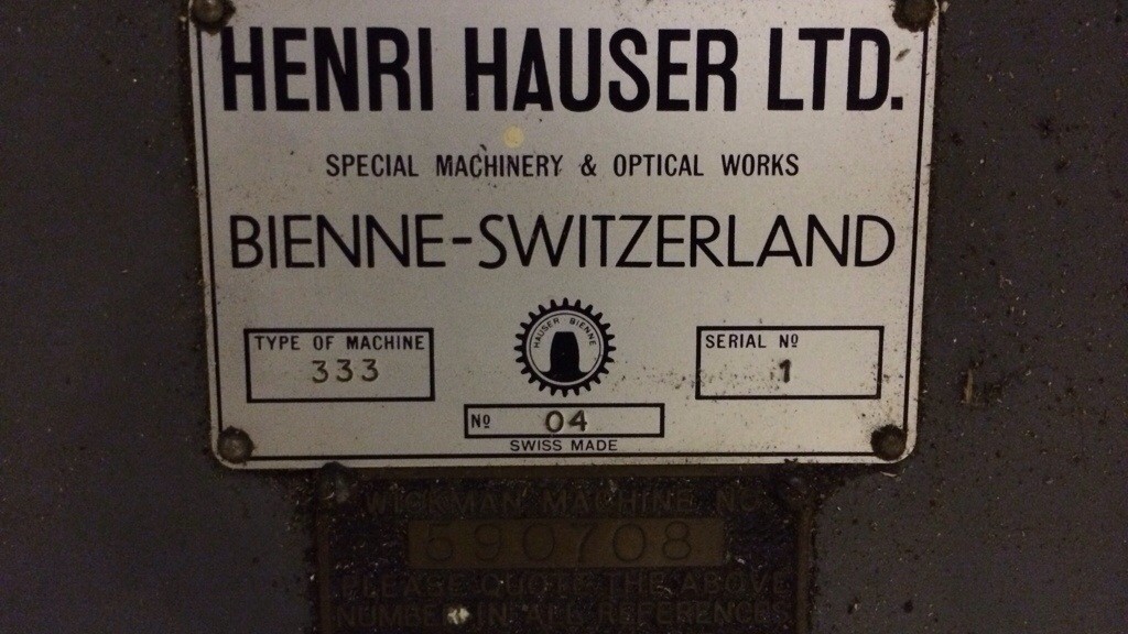
The Hauser 333 was made for cutting gears for street lamp timers, or so I have been told. It does this by having a ratchet wheel with the appropriate number of teeth attached to the workpiece spindle. A worm drive motor is constantly trying to rotate the workpiece spindle spindle through a clutch. The clutch slips until a solenoid releases the pawl, allowing the ratchet wheel to rotate until the pawl catches on the next tooth.
When it arrived in my workshop Continue reading New ratchet wheel for the Hauser 333

Restoring the Hauser 333 mill/pinion cutter

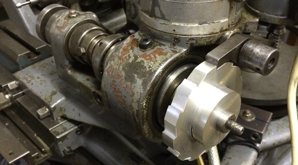
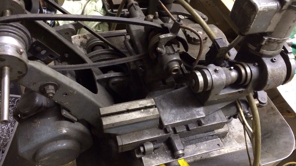
When I collected the Hauser it was in need of some TLC. It didn’t look as though it had been abused, just well used. Bit by bit I dismantled it until just the bare bones remained:

20140522-110856-40136549.jpg
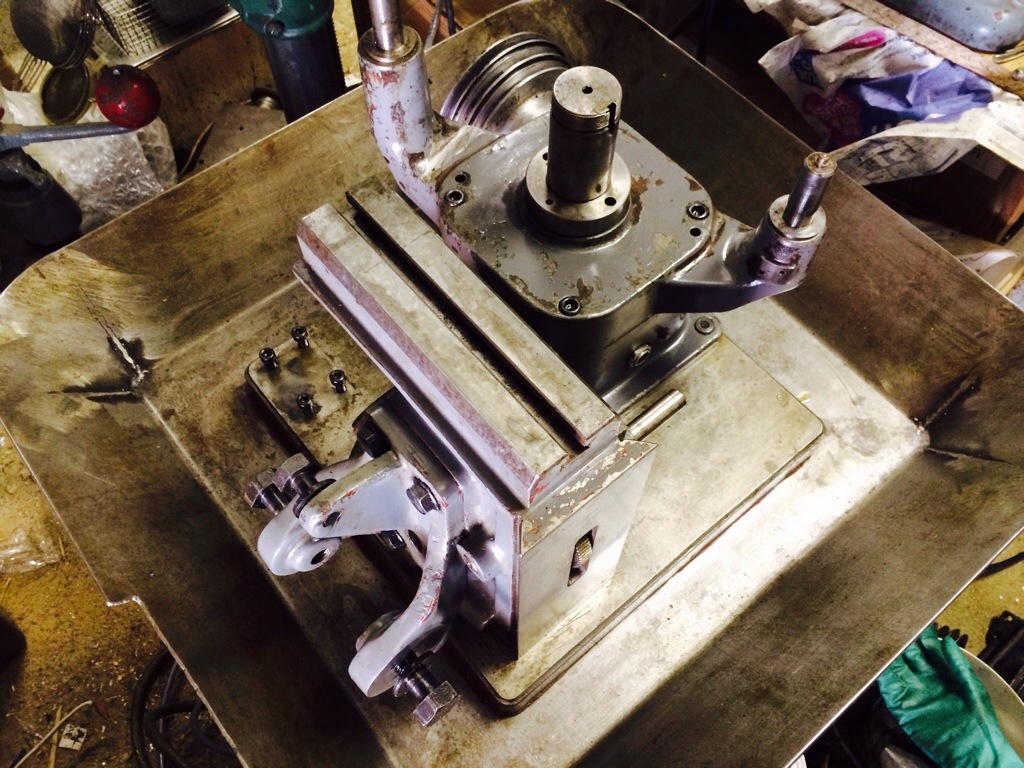
Once the parts had been cleaned, the reassembly was relatively quick and very satisfying. The next photo shows the vertical slide and X axis slides back in place. I discovered that the rack for moving the vertical slide was missing; if I decide I want to Continue reading Restoring the Hauser 333 mill/pinion cutter

New toys

While getting the workshop set up, I traded some of the Schaublin kit for other machines. I picked up an old Hauser mill, model 333, serial number 1, whose previous life was in a factory making timers. Wallace and Gromit would be proud: it’s a wonder of cams and levers.

20131123-172003.jpg

20131123-172018.jpg
My plan is to use it for pinion cutting, perhaps even wheel cutting if I can sort out a sensible way to index the spindle in which the work is held. My Continue reading New toys

Progress update – Schaublin lathe

Having been dabbling in lathe dealing over the past few months while trying to get the bits I wanted for my workshop, I’m now almost back at the point of having a working watchmaking lathe: a Schaublin 70 with lots of accessories. Probably not what most would consider a standard setup for a watchmaker but I think I will be exactly what I want: an accurate and rigid setup on which I can turn fine staffs and cut wheels and pinions. Continue reading Progress update – Schaublin lathe