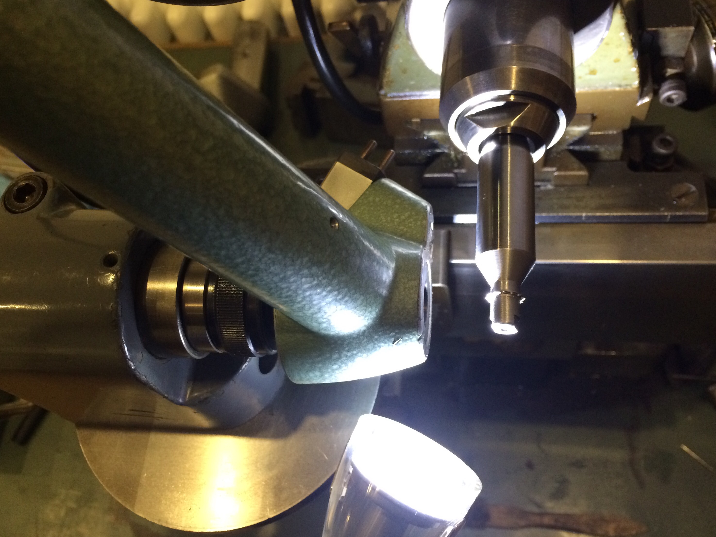
The faff to get everything set up for wheel cutting seemed endless: even after fitting up the electronic indexing head to the spindle I made a W12 wax chuck, then machined a blank arbour to take the cutter and made a nut to clamp the cutter in place. I used a dial indicator to set the indexing spindle perpendicular to the cutter axis:
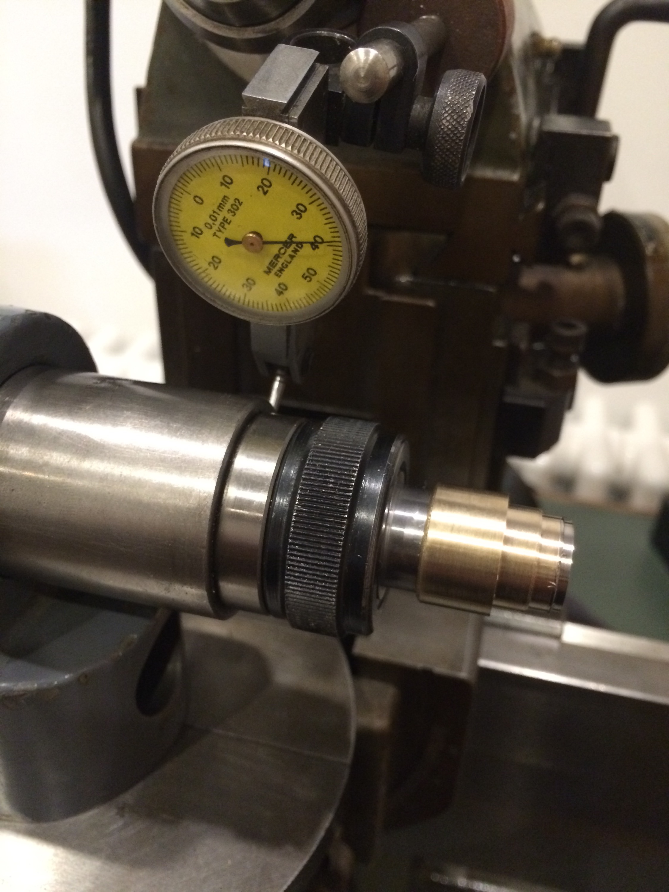
Then put the centring microscope in the indexing spindle in order to get the cutter dead centre:
It was at this point that I turned on the motor and discovered the biggest problem so far: the spindle wasn’t running true. The deviation was about 0.15mm, but this could be made very close to zero by slight sideways pressure with a finger. I was hopeful that I can adjust this out, so I set about dismantling the spindle:
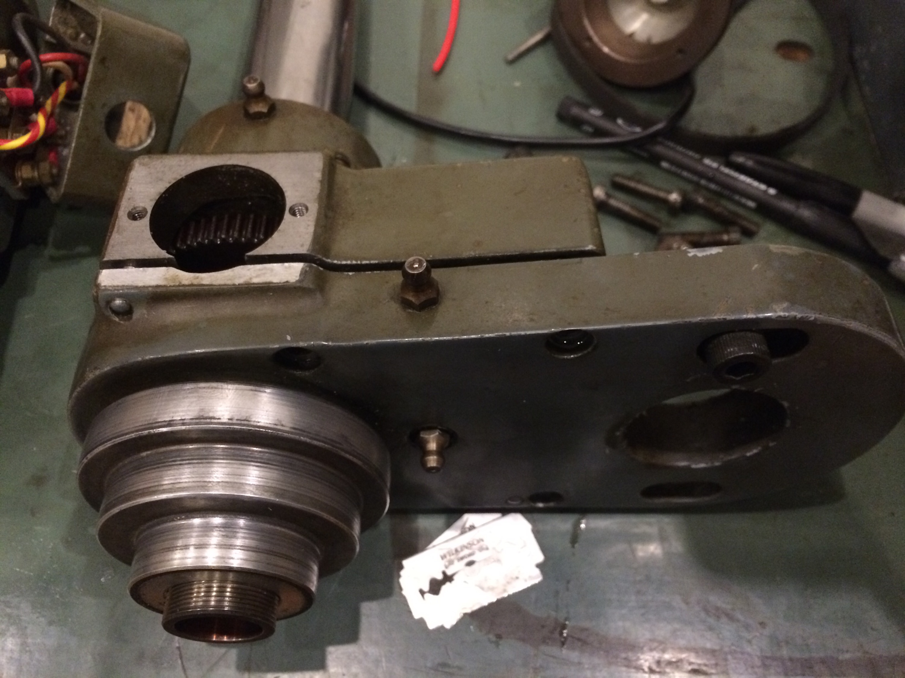
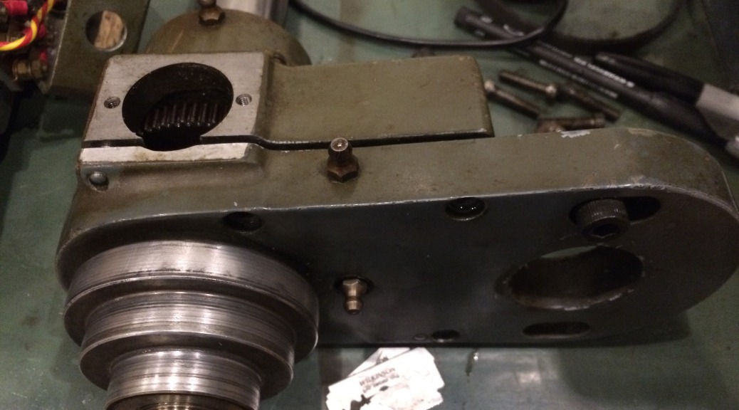
The first challenge was removing the motor pulleys; the were so tightly held by years of oil that a gear puller was needed, with a piece of aluminium bar in the centre of the pulleys for the puller to bear on.
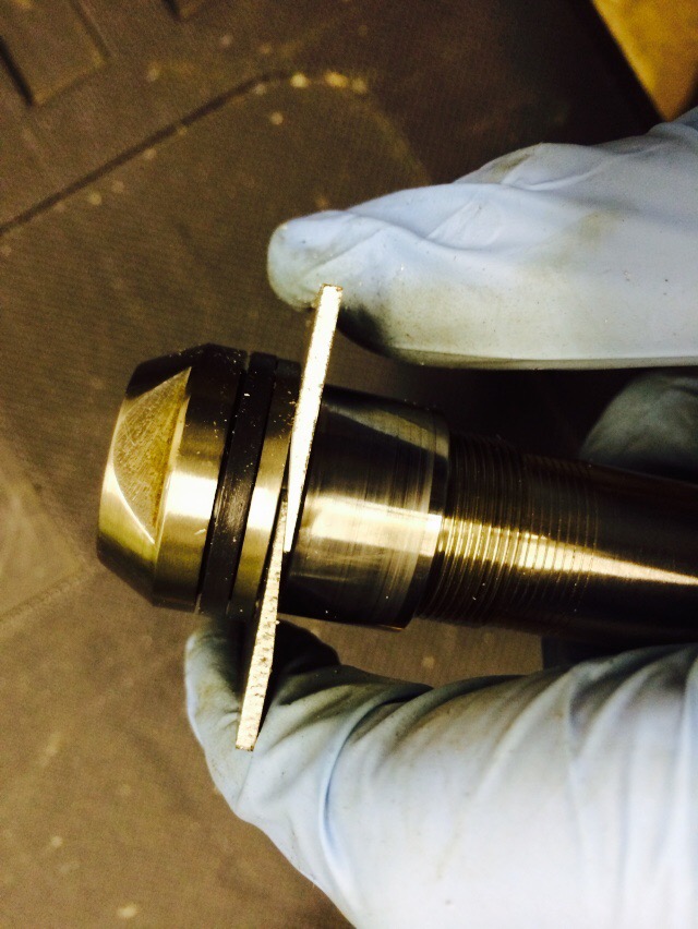
The razor blades were slipped into the crack between the case sides and then progressively fatter wedges (screw drivers) driven between the razor blades. The blades acted to spread the load of the wedge, so avoiding damaging the case while trying to release the sides from the dowels. Eventually it came apart:
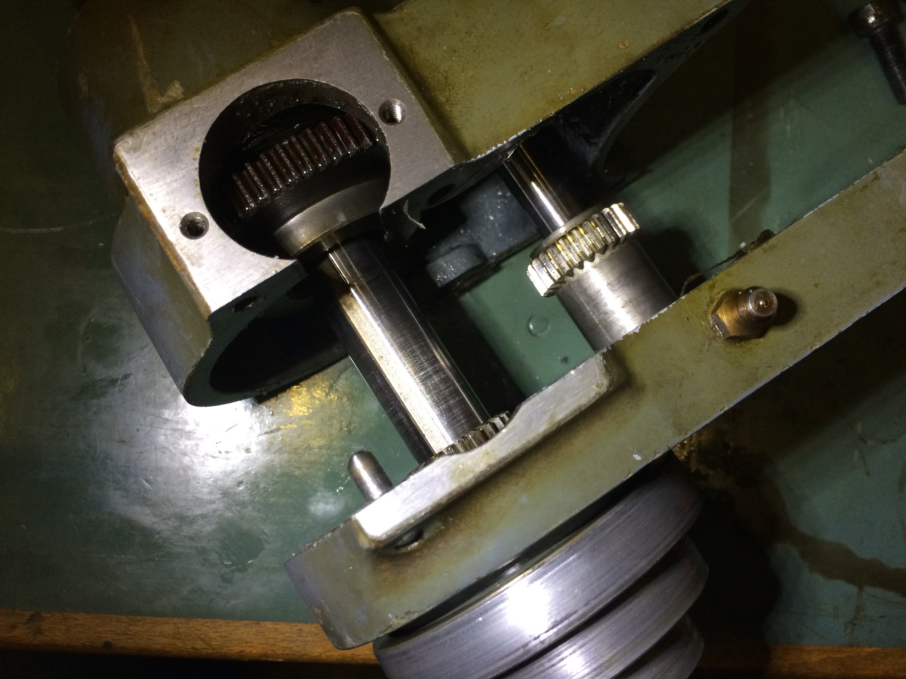
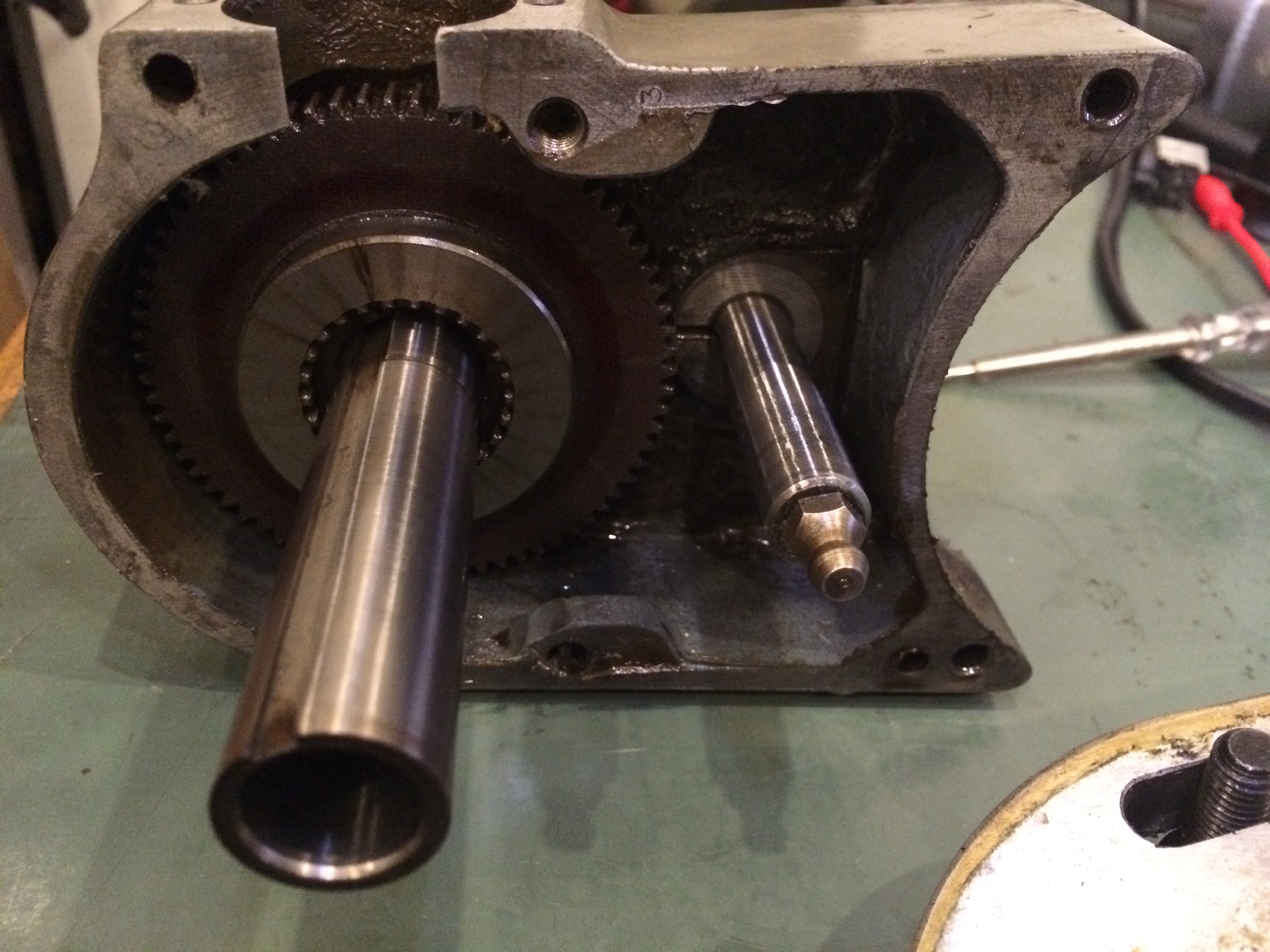
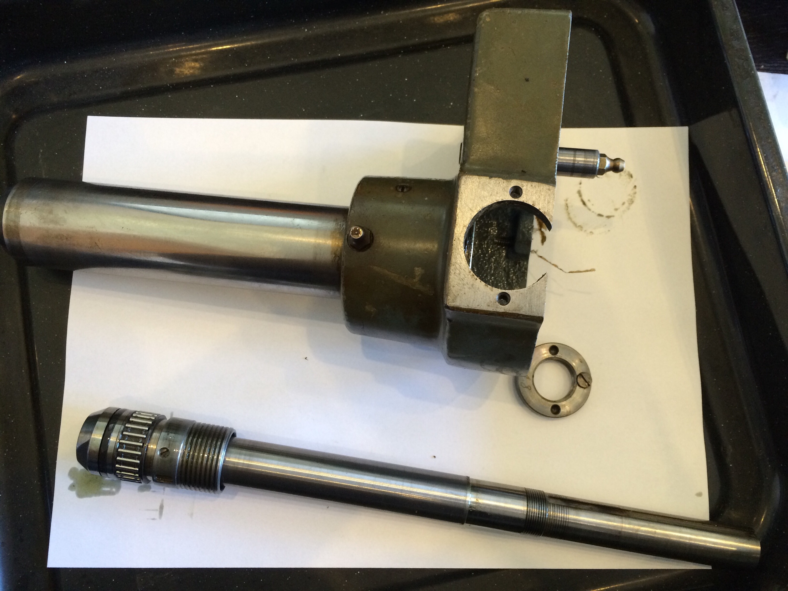
The side with the spindle, on which is mounted a fibre gear:
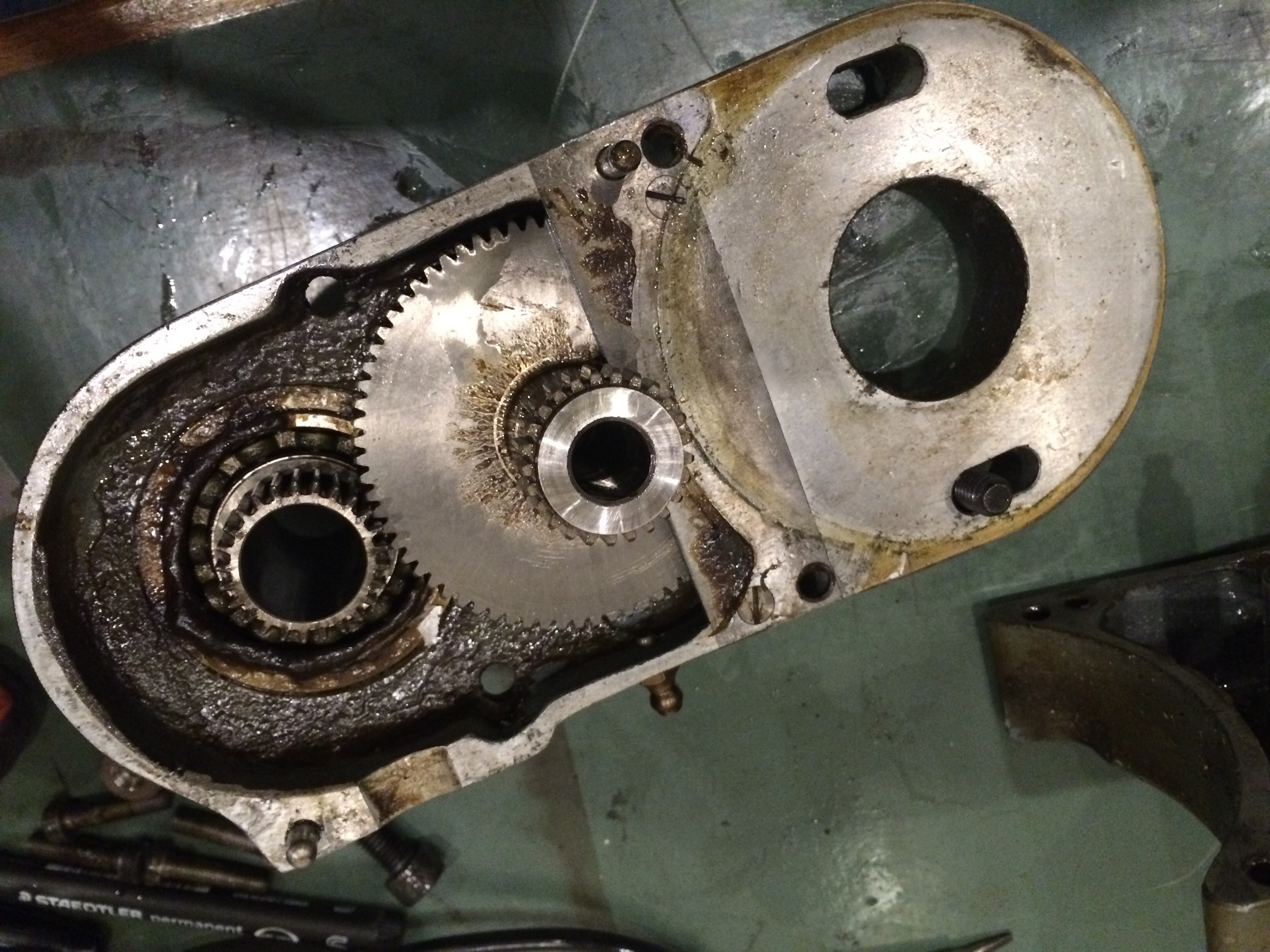
And the other side, with a bearing that needed a good clean:
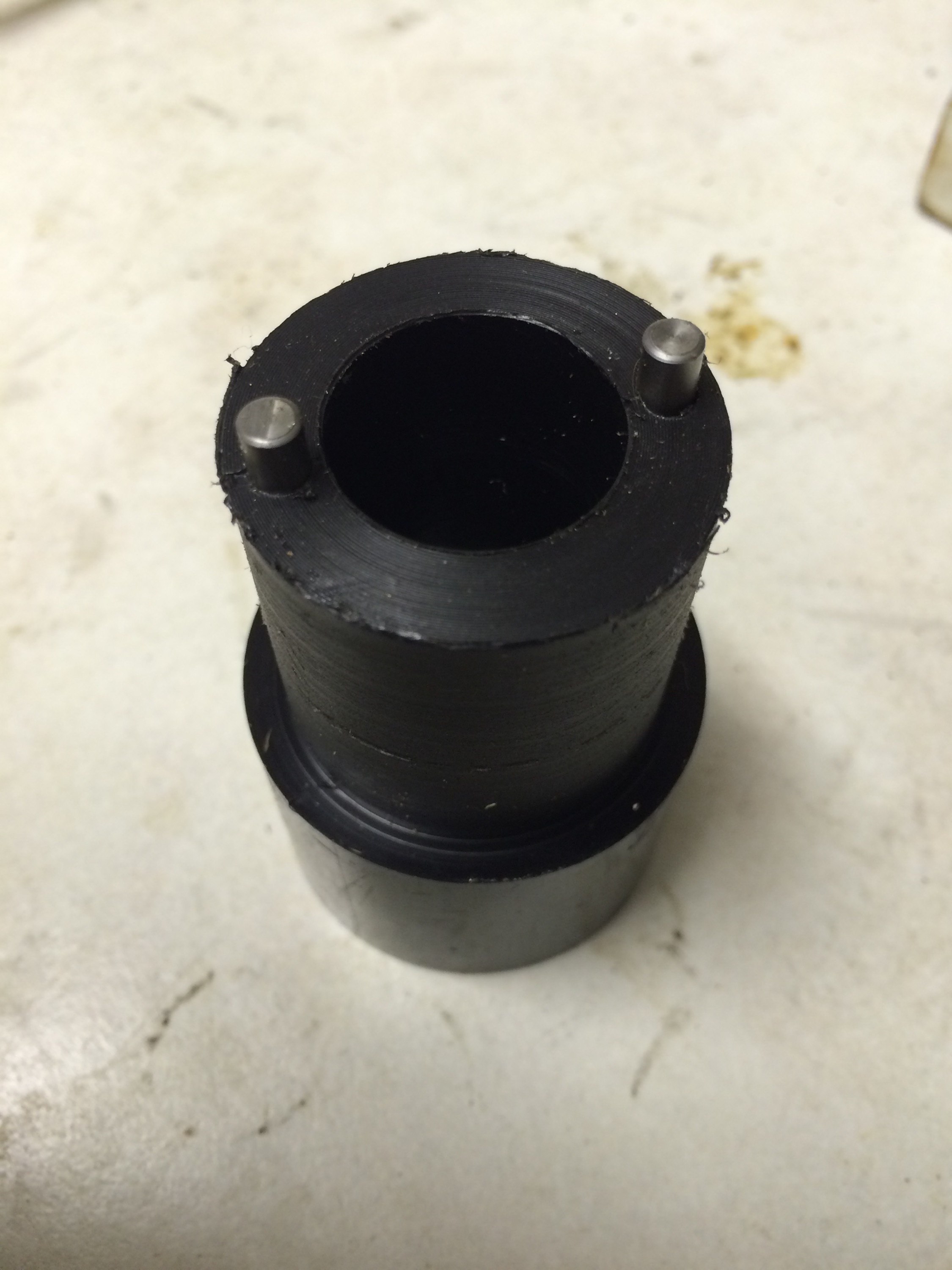
Once the fibre gear was removed from the spindle, the next challenge became apparent: removing the lock nut(s) on the spindle would require a spanner with two pins, able to reach approximately 10mm down a 35mm diameter hole. This I had to make. I think this takes the biscuit for most time consuming fix, having to make a tool in order to fix a machine that I can then use to make parts.
Here is the simple but effective tool, mostly nylon with two 4mm diameter steel pins. I had roughly measured the spacing of the pins as 27.5mm, which turned out to be about 1mm too close together. I will drill two more holes at the correct spacing, again putting the tube in the chuck and using the tool to scribe a diameter.
The spindle came apart easily to reveal a set of needle roller bearings. According to the manual, these are on a slight taper and the retaining nut can be tightened to take up some radial movement, however I think the adjustment was already at its maximum.
A quick test after reassembly suggests the runout was now down to 0.03mm, which is not bad but significantly worse than it could be. Using a long cutter arbor in the spindle increased the runout slightly to 0.04mm.
I spent a couple of days investigating solutions to reducing the runout closer to the original 0.005mm. One idea was to have the spindle and housing ground back to round, then hard chrome plated in order to increase the size back to the original, then finally ground back to size. However, hard chrome plating isn’t cheap: each hour in the tank will cost £100 and deposits about 0.02mm.
On the spindle I have, the inner bearing surface is a ring with an internal taper, such that tightening a nut pushes the ring further up the taper, whereupon it expands slightly (up to 0.02mm) to take up play. The wear was clearly visible on the ring. This ring was, of course, firmly stuck on the taper, so another tool was needed. I fashioned a matched pair of wedges out of aluminium that allowed me to pop the ring off its taper with no chance of damage to the spindle.
What I ended up doing was to have both the spindle and housing ground to accept a slightly larger set of needle rollers, actually an imperial set that was approximately 25.4 x 30.162 x 12.7 mm. After reassembly the runout on a cutter arbor in the spindle was measured: less than half a division deflection on a 0.01mm per division indicator, so back to the original 0.005mm tolerance.