At last, more progress on the tool making. After breaking the cutting tool while making the hob for the worm wheel, I started looking around for off-the-shelf worm drives. A low backlash one came up on eBay for $100 including a stepper motor, so I jumped.
My original plan with the bought drive was to bore out the centre of the worm wheel so that it would fit on the spindle of the direct dividing head (or indexing head) of the Aciera F1 and allow the drawbar to pass through. As it turned out, this wouldn’t work as the spindle diameter is 18mm and the boss on the worm wheel, which is held in bearings, was around 16mm diameter. So, an adaptor was needed.
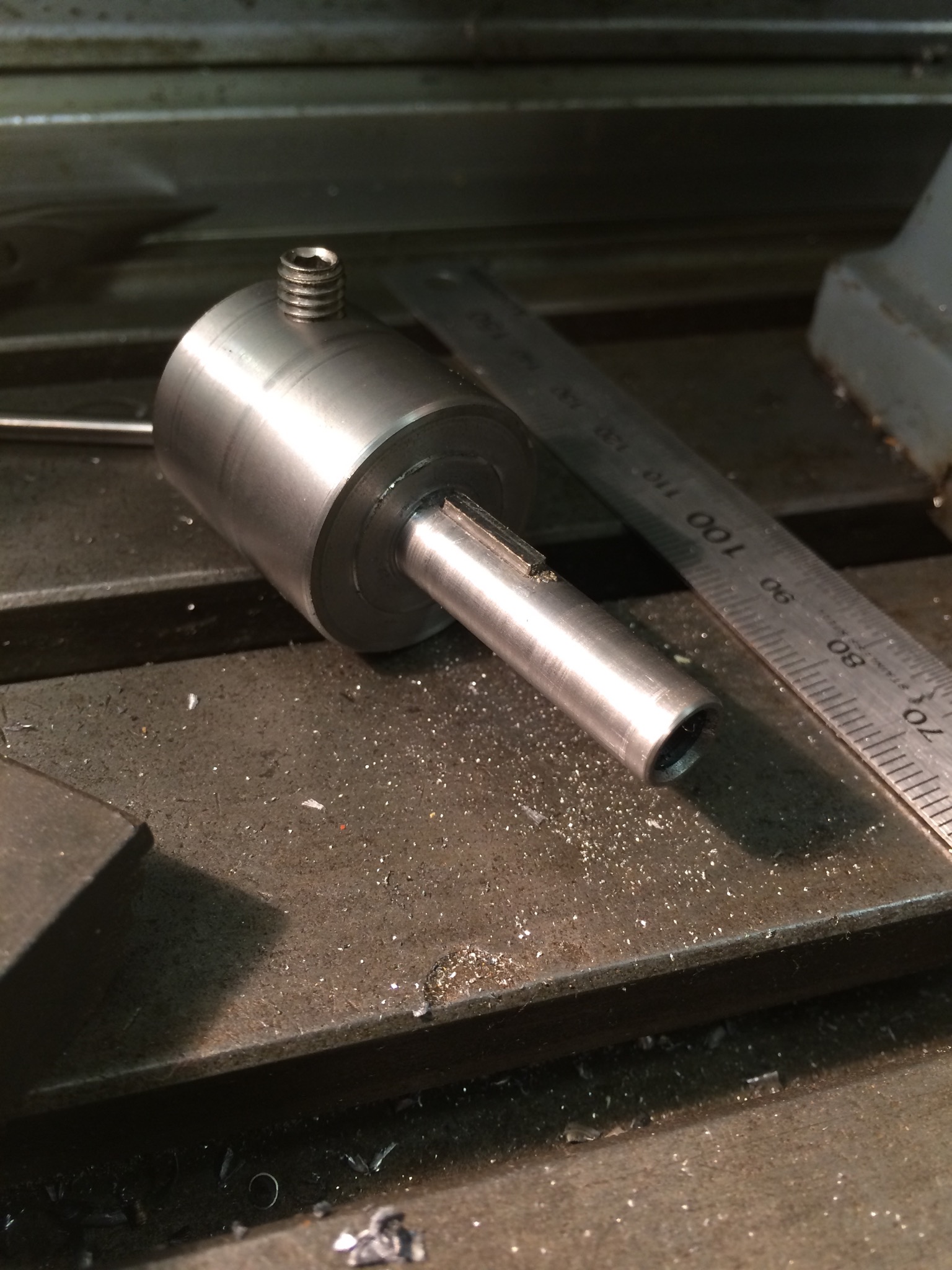
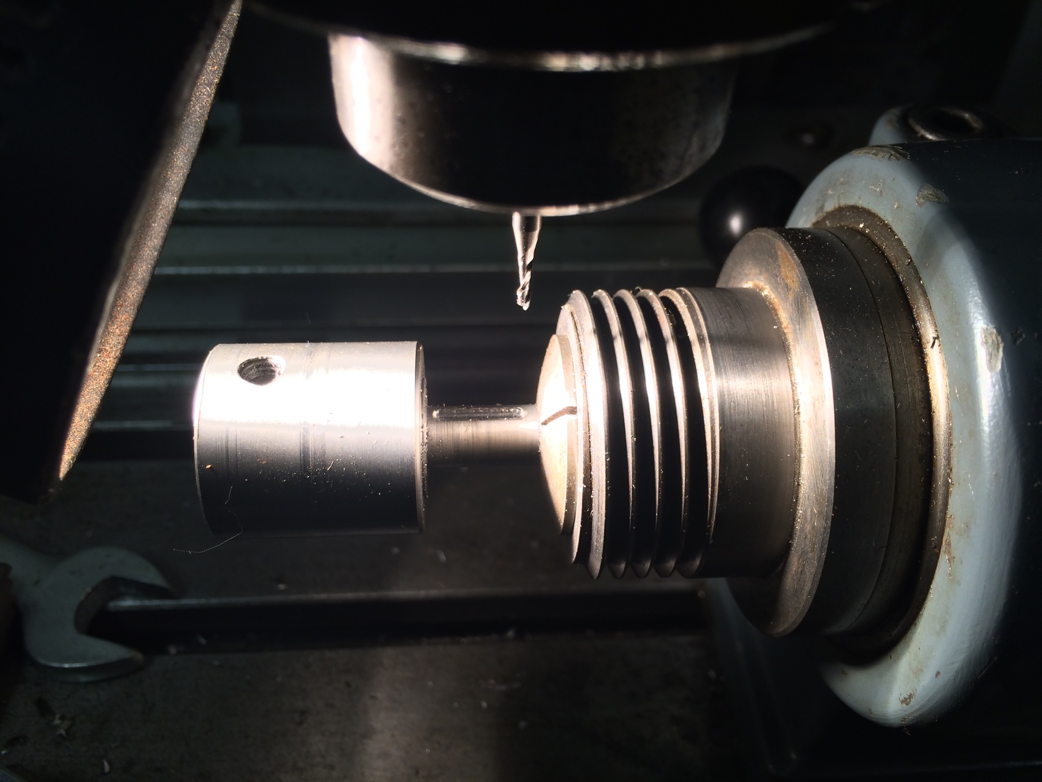
This is the finished adaptor. The larger end is bored out to 18mm to give a very snug fit on the spindle, the thin end was turned to 8mm to give a very snug fit inside the bore of the worm wheel (the clearance of both is probably around 0.01mm, since this is how much was removed in the finishing pass to make the difference between the components not fitting and sliding together). There is a 5.5mm hole through the middle to allow a thin shaft to pass through. This shaft will have an M5 thread on one end, to screw into a drawbar that I modified, and a hand wheel on the other so that the collet can be tightened.
A slot was milled in the thin end of the adaptor to take a length of 2mm square key steel from the keyway of the worm wheel. The key was glued in place on the adaptor and then milled down to the required height.
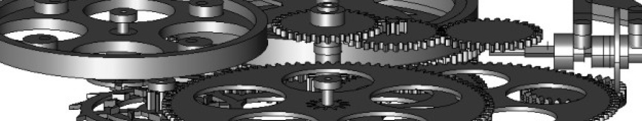
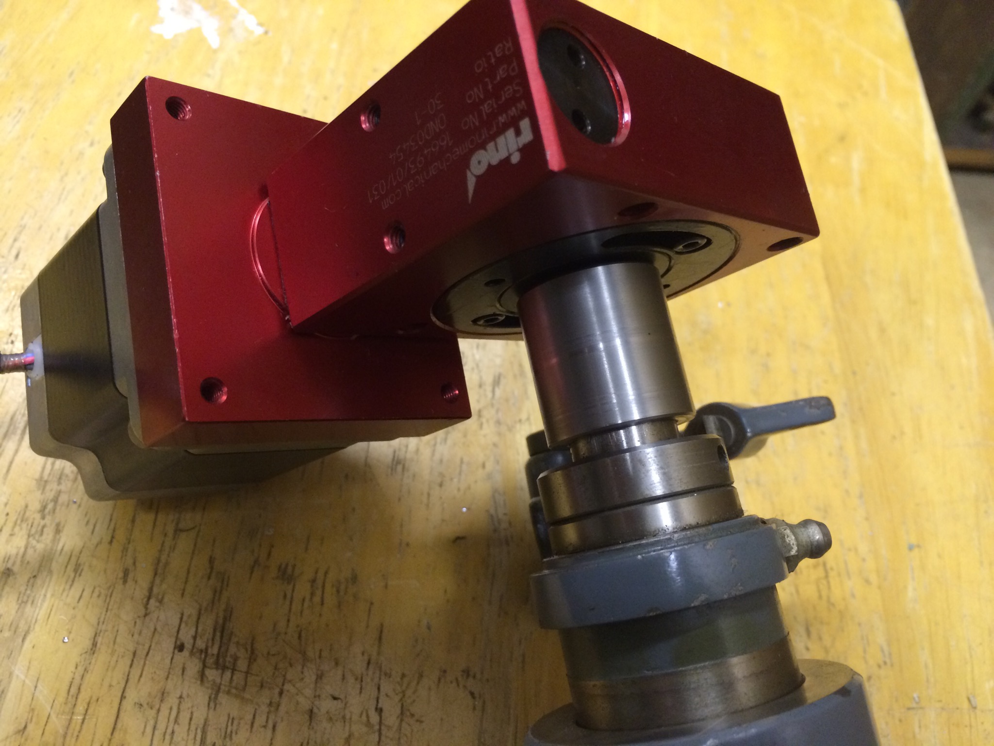
The resulting assembly looks like it should do exactly what is intended.
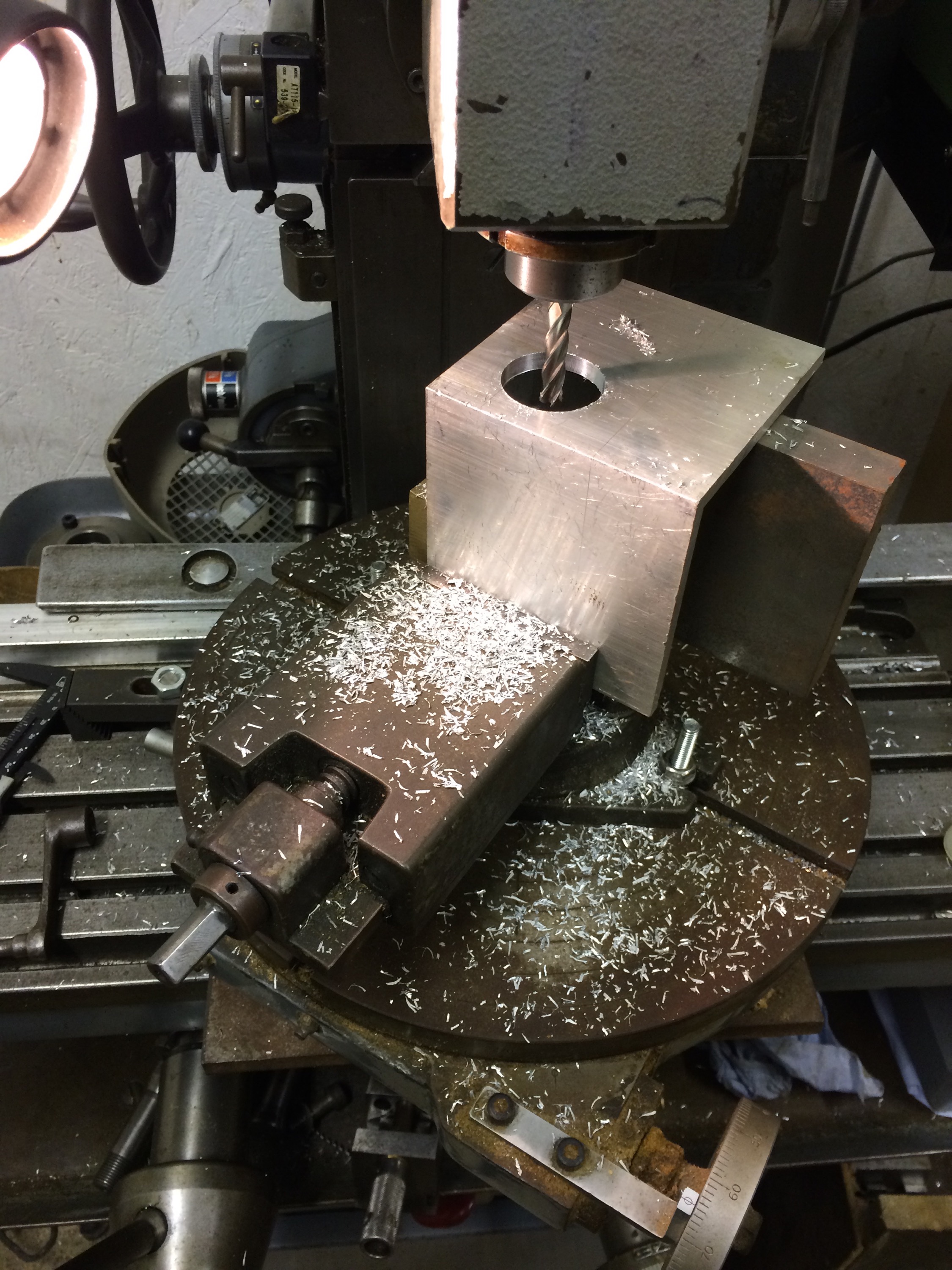
After some deliberation, I decided to use a piece of angle aluminium to mount the worm drive. One side will clamp onto the static outer of the spindle, the other will extend towards the worm drive and provide a surface onto which the worm drive can be mounted. The first step was to bore a 35mm hole to accept the spindle, not easy with such a large piece of angle. I opted for drilling as big a hole as I could (25mm) on the pillar drill, then mounting the angle on a rotary table on the Aciera F3 to finish the hole to size.
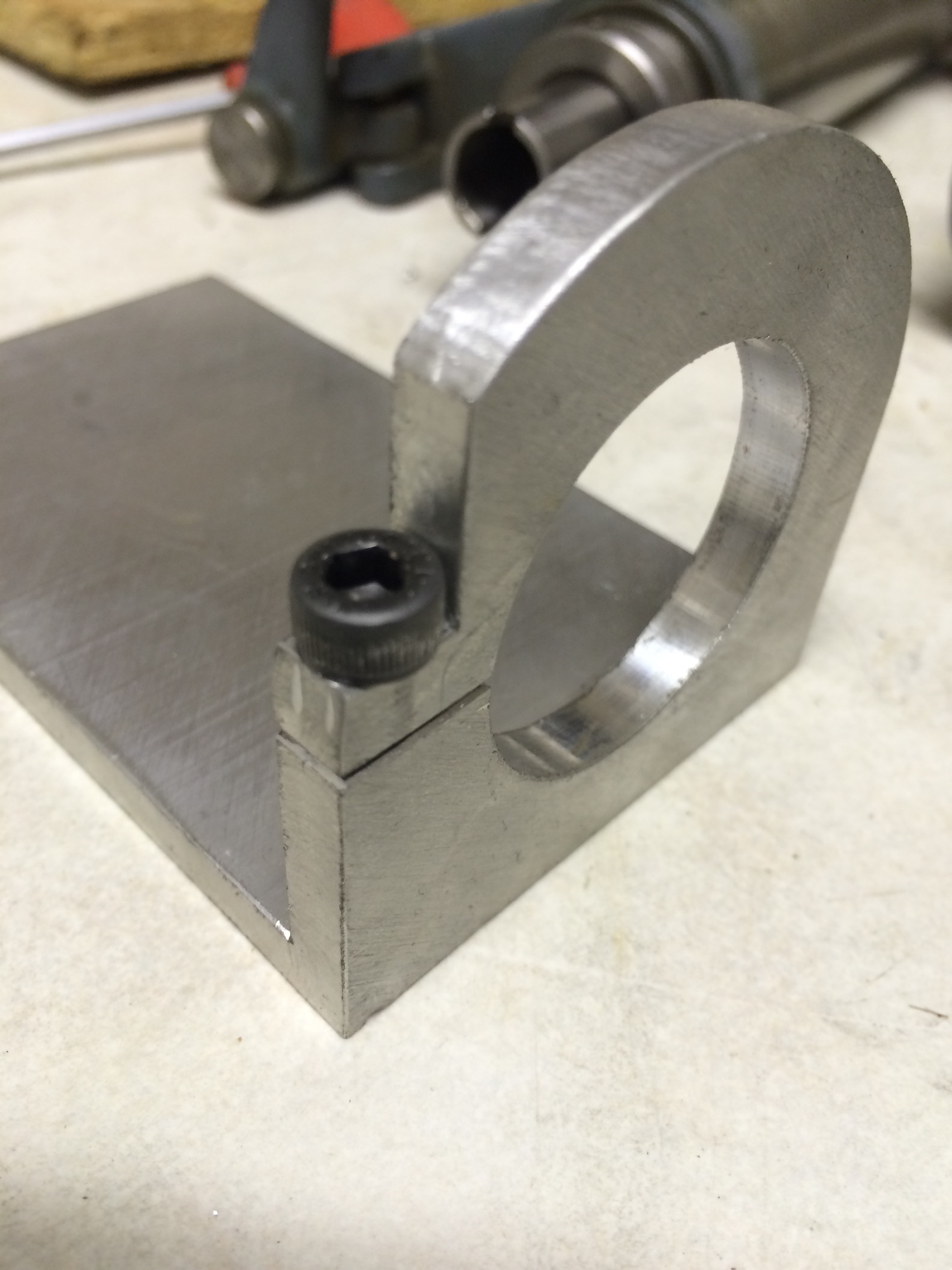
After finishing the hole so that the spindle just slipped in, the outer edge of the bracket was rounded off, making a 180 degree arc concentric with the hole. In order to make the clamp arrangement, a flat was milled part way around this arc, then a hole centre drilled, drilled, counter-bored and tapped for an M5 cap head screw. The final machining was to mill the long sides of the angle perpendicular to the face with the hole. The finished bracket is shown below.
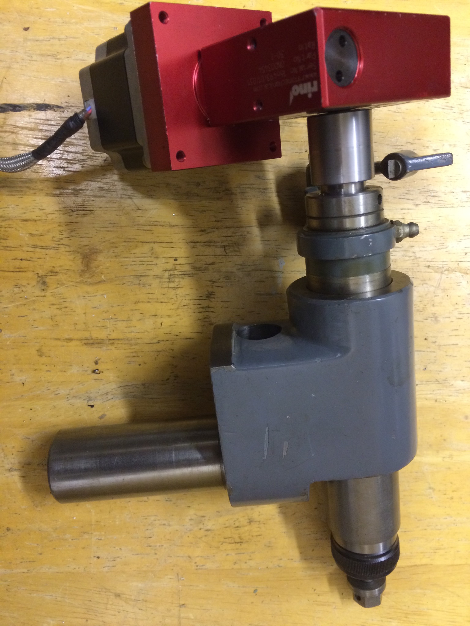
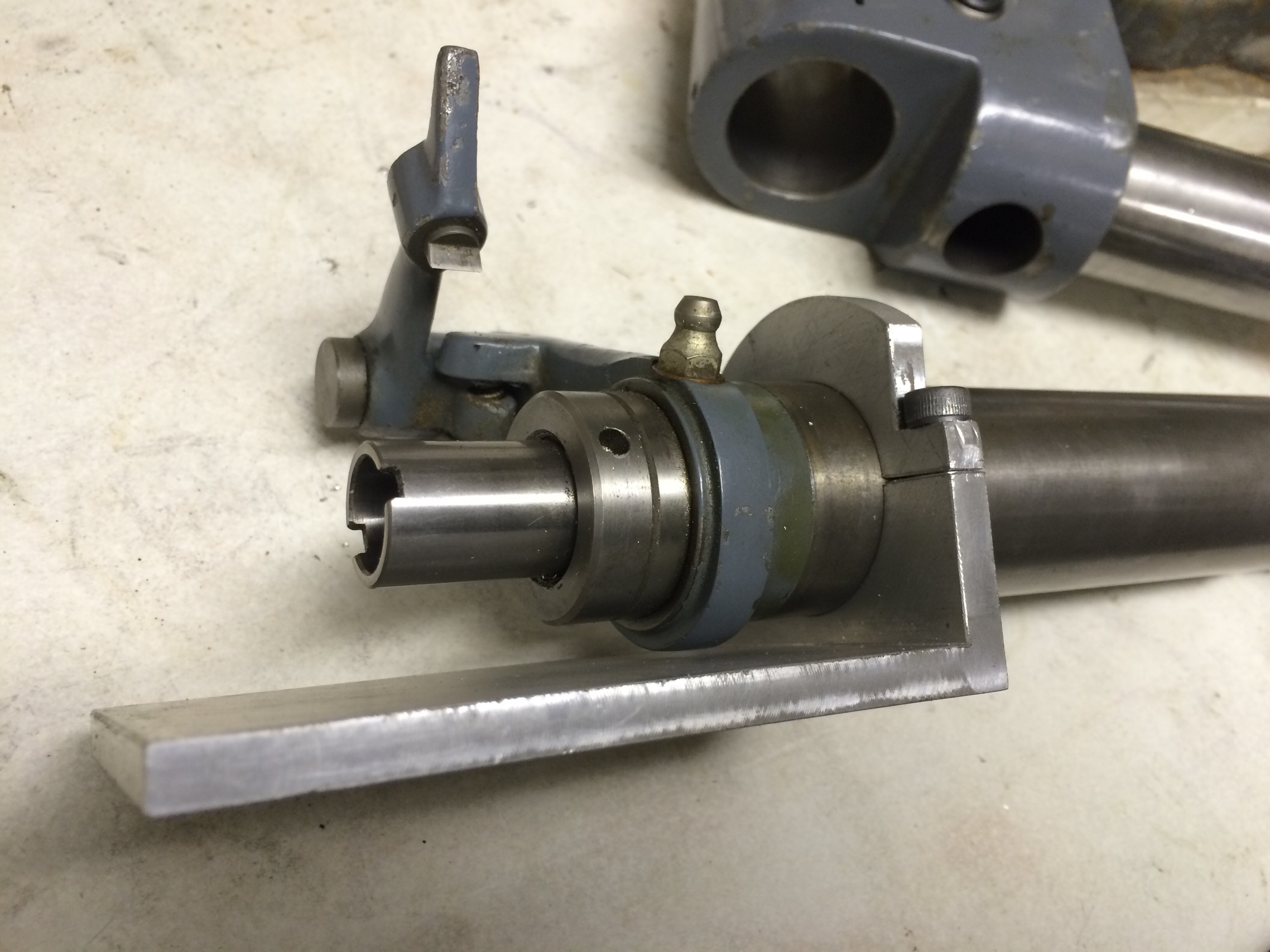
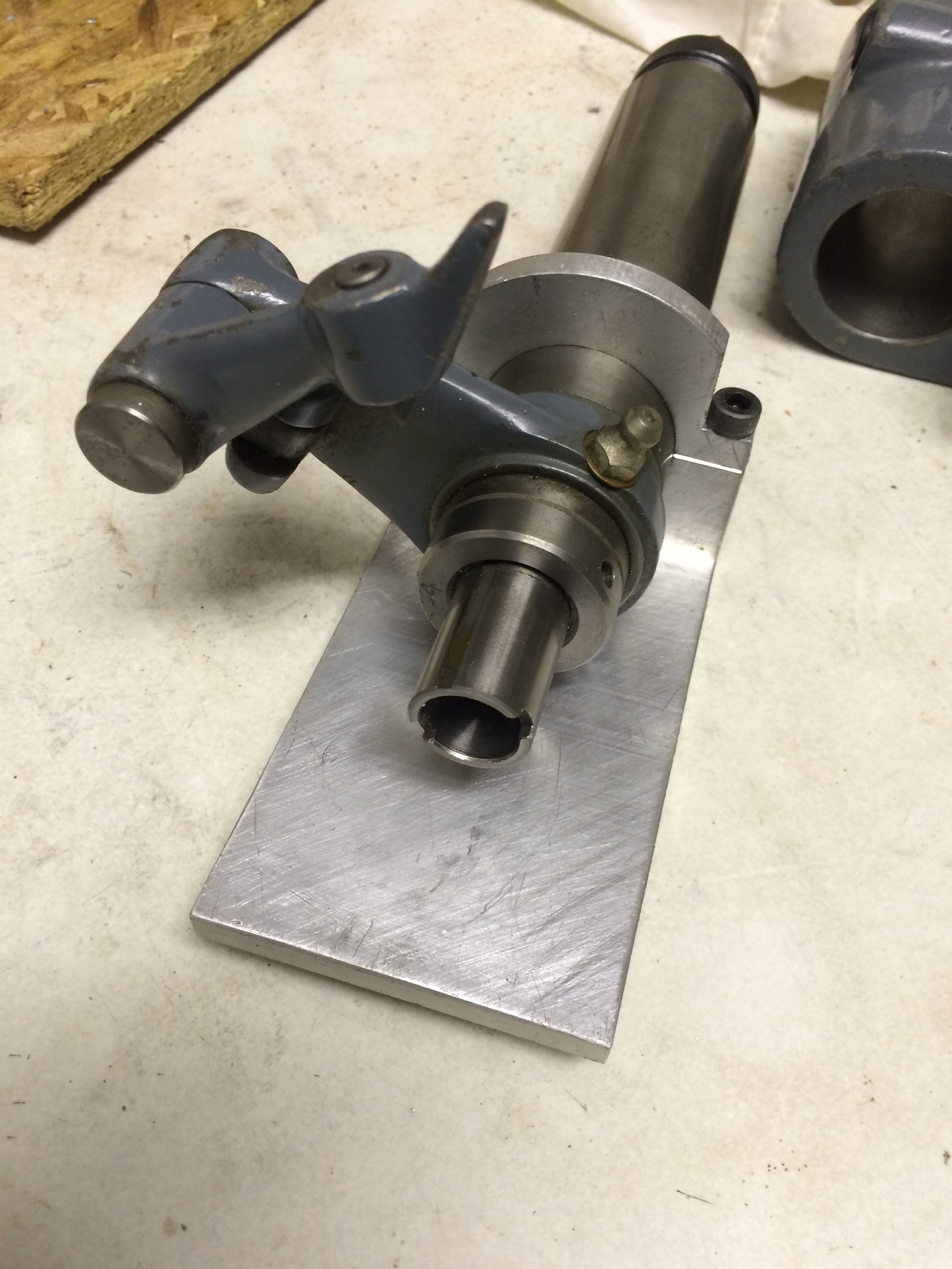
Mounted on the spindle:
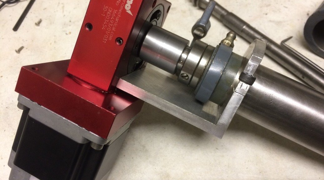
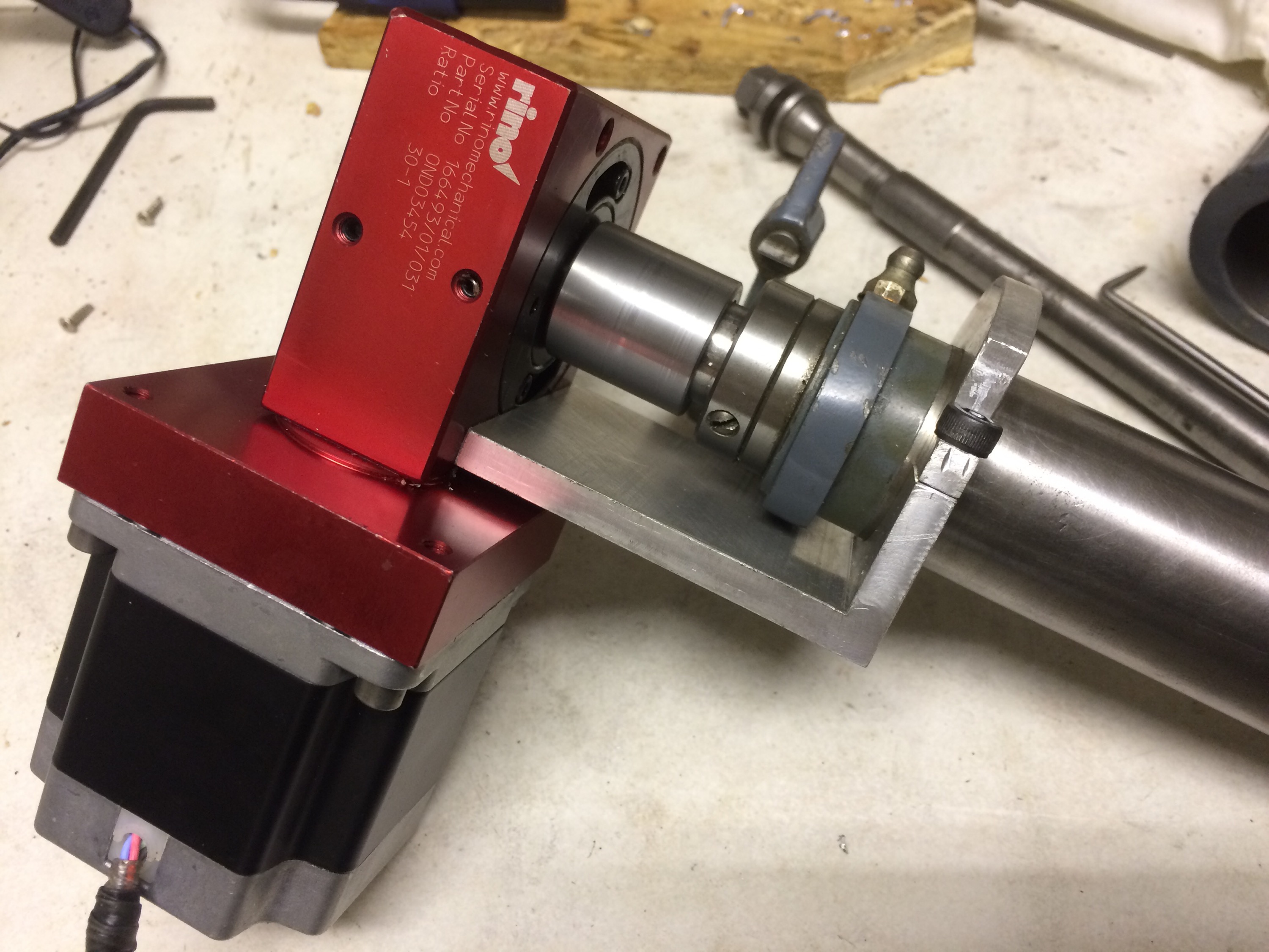
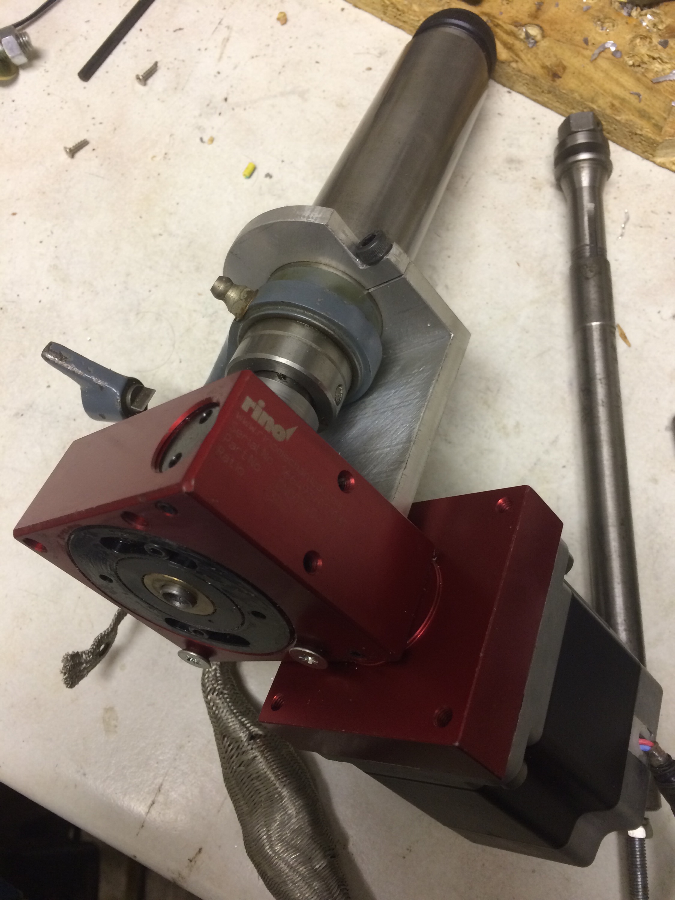
And now trimmed to length and attached to the worm drive:
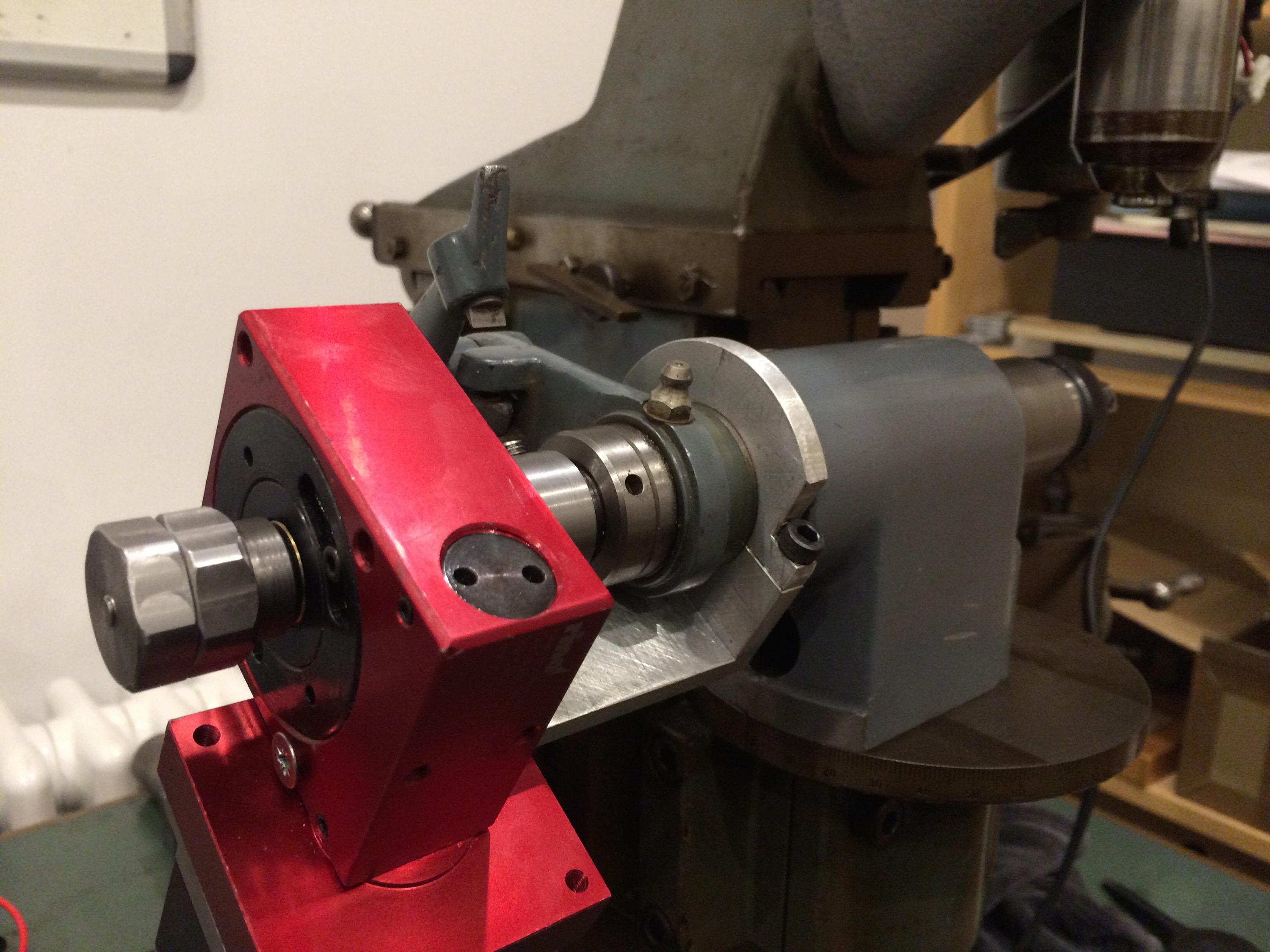
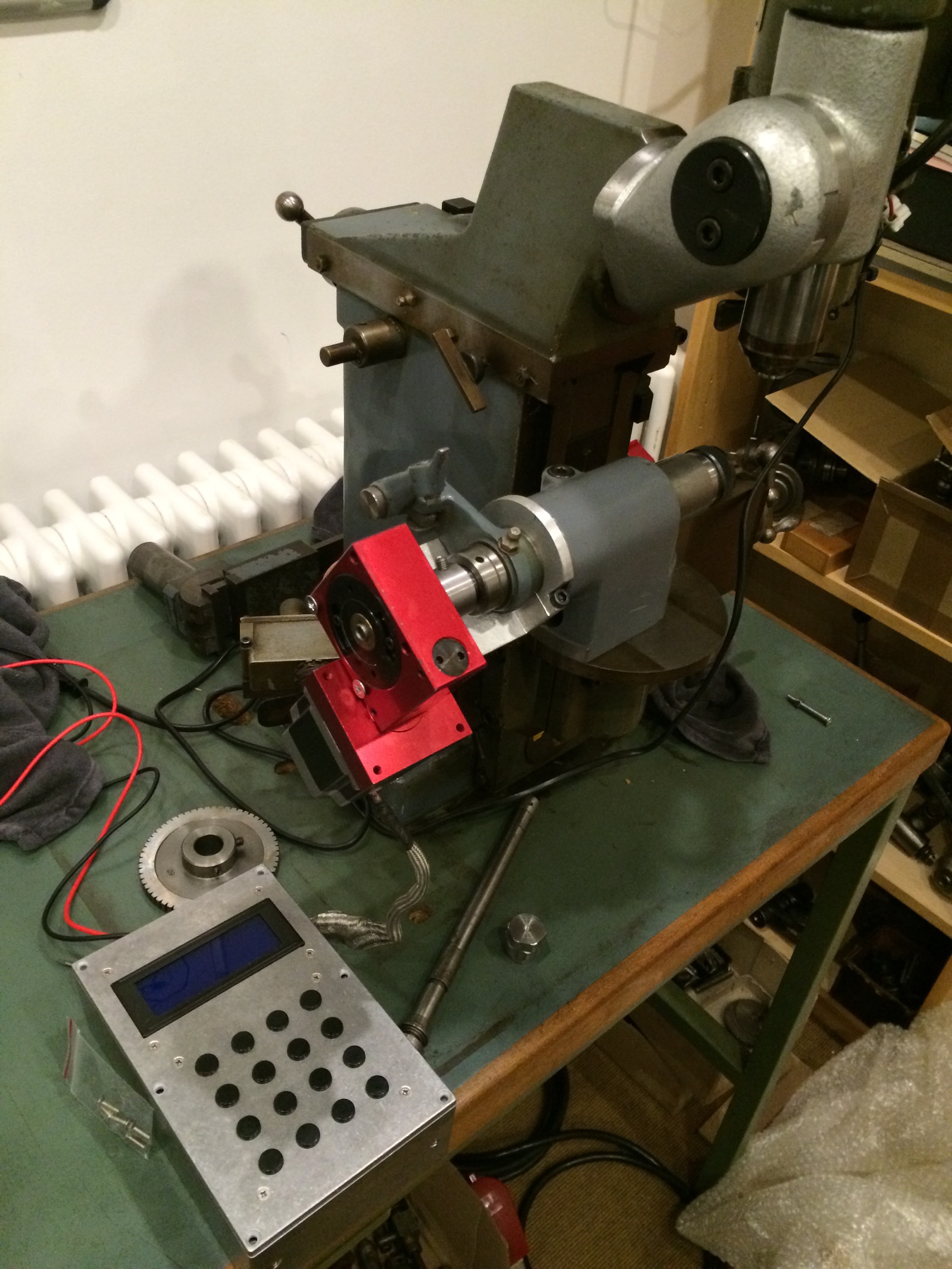
And finally in place on the F1, with the Ward controller next to it, cased up and ready to go.
What won’t be visible in the spindle in these images is the drawbar, which turned out to be one of the more tricky parts of the project. I was lucky enough to have part of a drawbar spare, so it was modified to fit within the spindle. The difficulty is the limited bore through which the drawbar can pass: after fitting the adaptor to interface the worm wheel to the spindle, the maximum bore through the worm drive is about 5.5mm. A hole was bored and tapped to M5 in the end of the drawbar itself, with the aim of making a up a bar, diameter 5.5mm in the middle and threaded M5 at both ends, which would screw (and be glued) into the drawbar, pass through the worm wheel, and leave a threaded section the far side. Onto this threaded section will screw two large nuts, so that they can be locked against each other to allow the drawbar to be turned.
The nuts were made without a hitch, by turning and boring to size and then milling 6 flats using the F3. Threading the bar proved a little more tricky, with the first attempt being bent in the process. I resorted to using a length of M5 threaded bar held in the drawbar with thread lock, with a washer to set the spacing between the end of the drawbar and the inside of the adaptor.
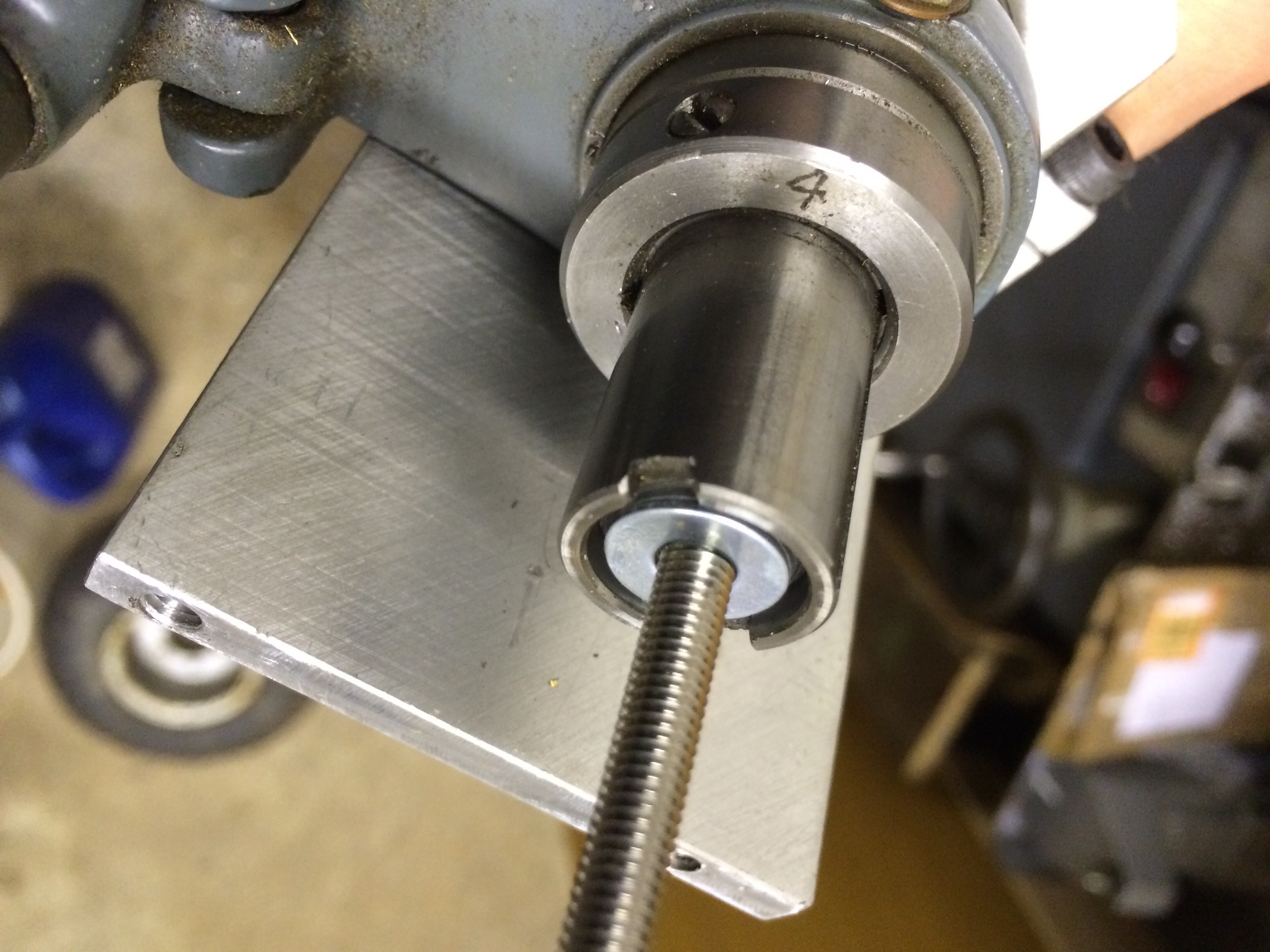
The lock nuts I had made then spun nicely onto the threaded bar and, when locked together by hand, allow the drawbar to be rotated to pull in a collet. Project complete.