After some deliberation, I decided that I would attempt to make my own worm gear and wheel for my electronic indexing device. While it’s possible to buy the gear and wheel from companies such as HPC, the low backlash type that I want commands a high price. Besides, it’s an interesting project in itself.
Some searching on the web got me the basic calculations for the sizes of gear and wheel, based on my desired ratio of 36:1. This ratio was chosen as, when multiplied by the 200 steps per revolution of a standard stepper motor, most tooth counts need integer numbers of steps per tooth and should therefore be error free (from that perspective anyway).
While looking for the sizing calculations, I also came across a site that said it was essential to use a hob slightly larger than the worm gear when cutting the wheel.
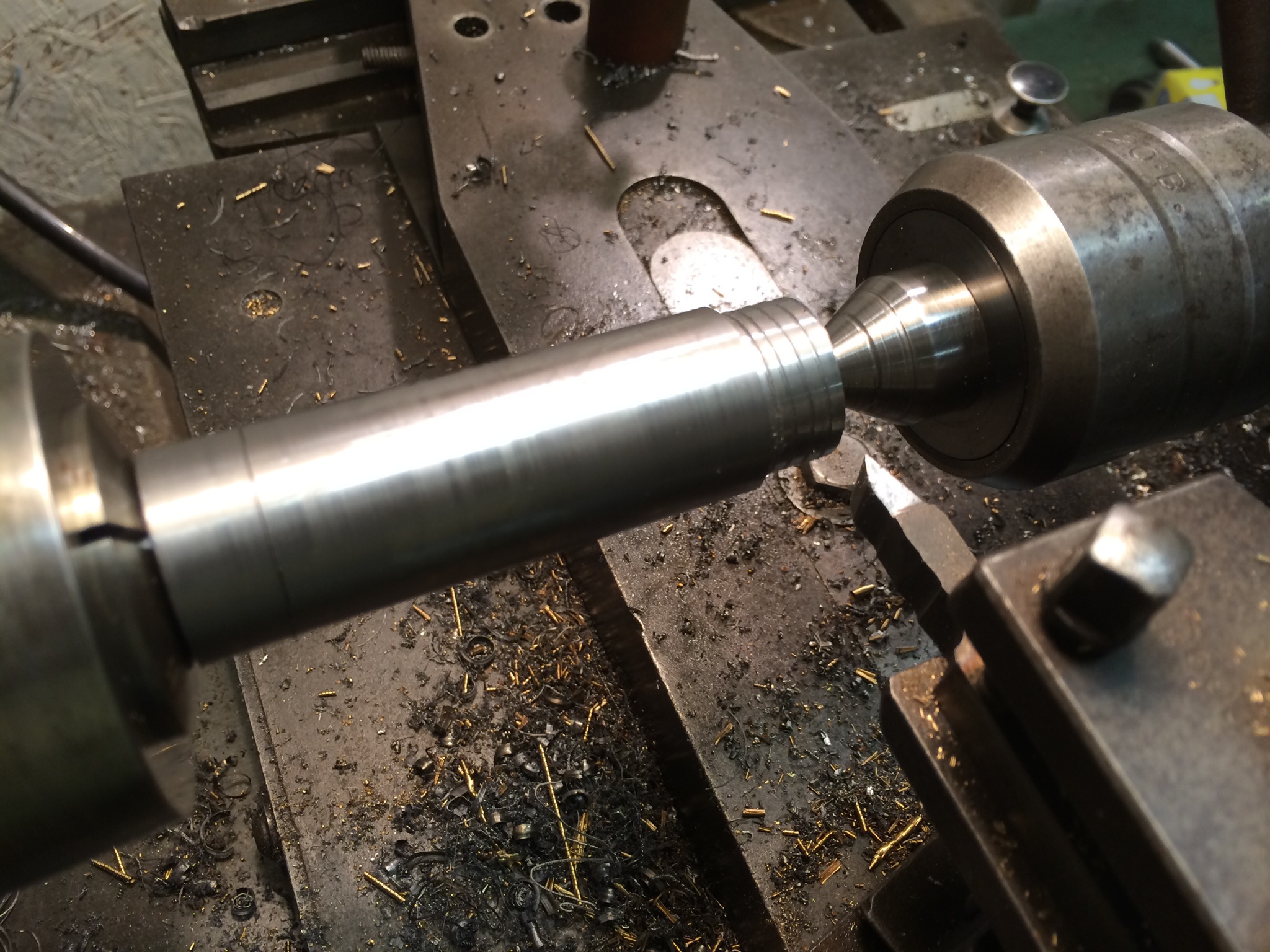
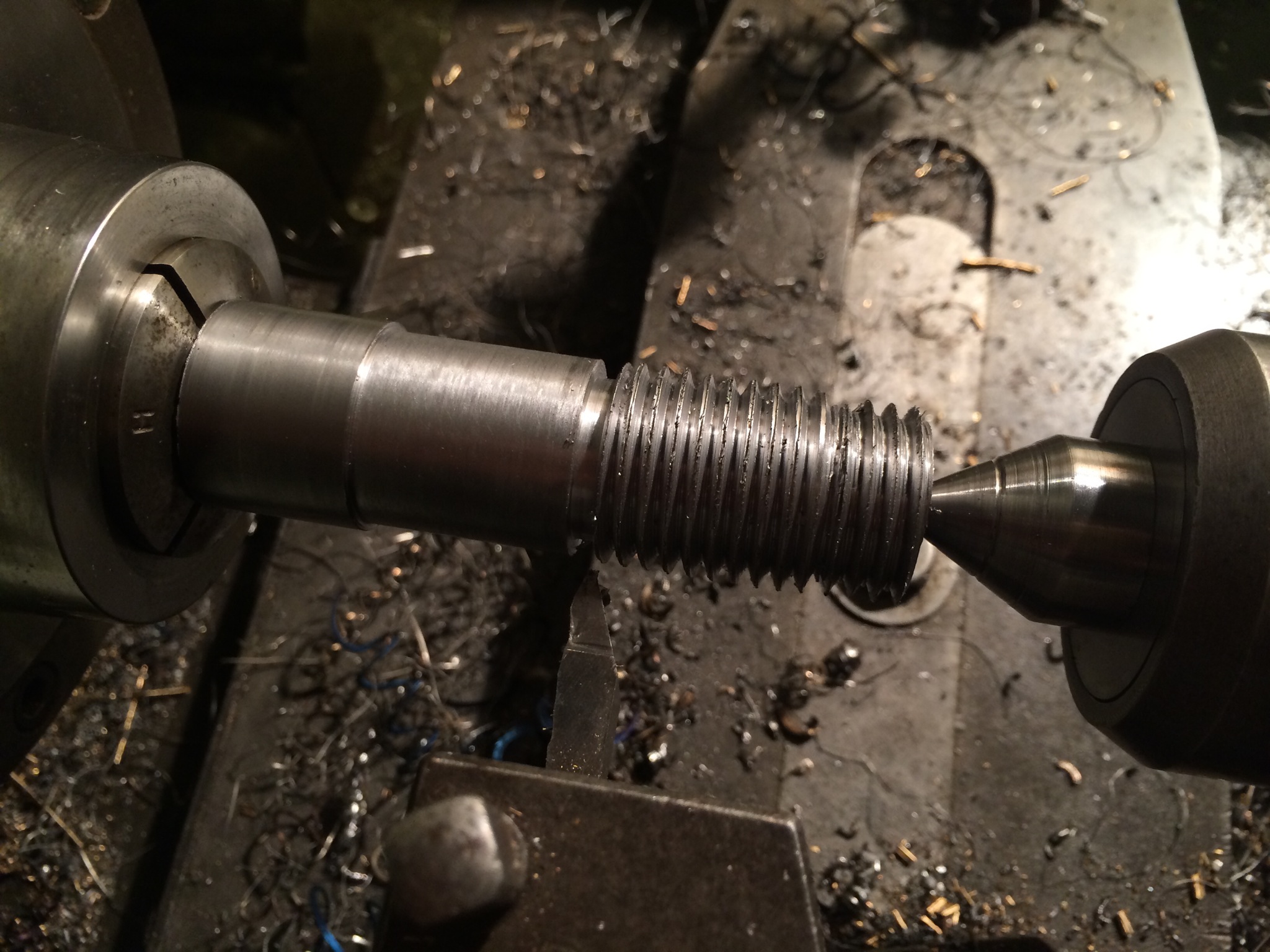
I turned a piece of 25mm tool steel bar down at one end so that I could hold it in a collet both on the lathe and in the mill for hobbing, supported by a centre in a hole at the other end. This was to become the hob. I then turned a portion of the bar at the tailstock end down to the full diameter of the worm gear. This was then threaded with the maximum pitch thread my lathe will cut just using the gearbox, 2.5 mm. From this I could judge how much larger I could make the hob.
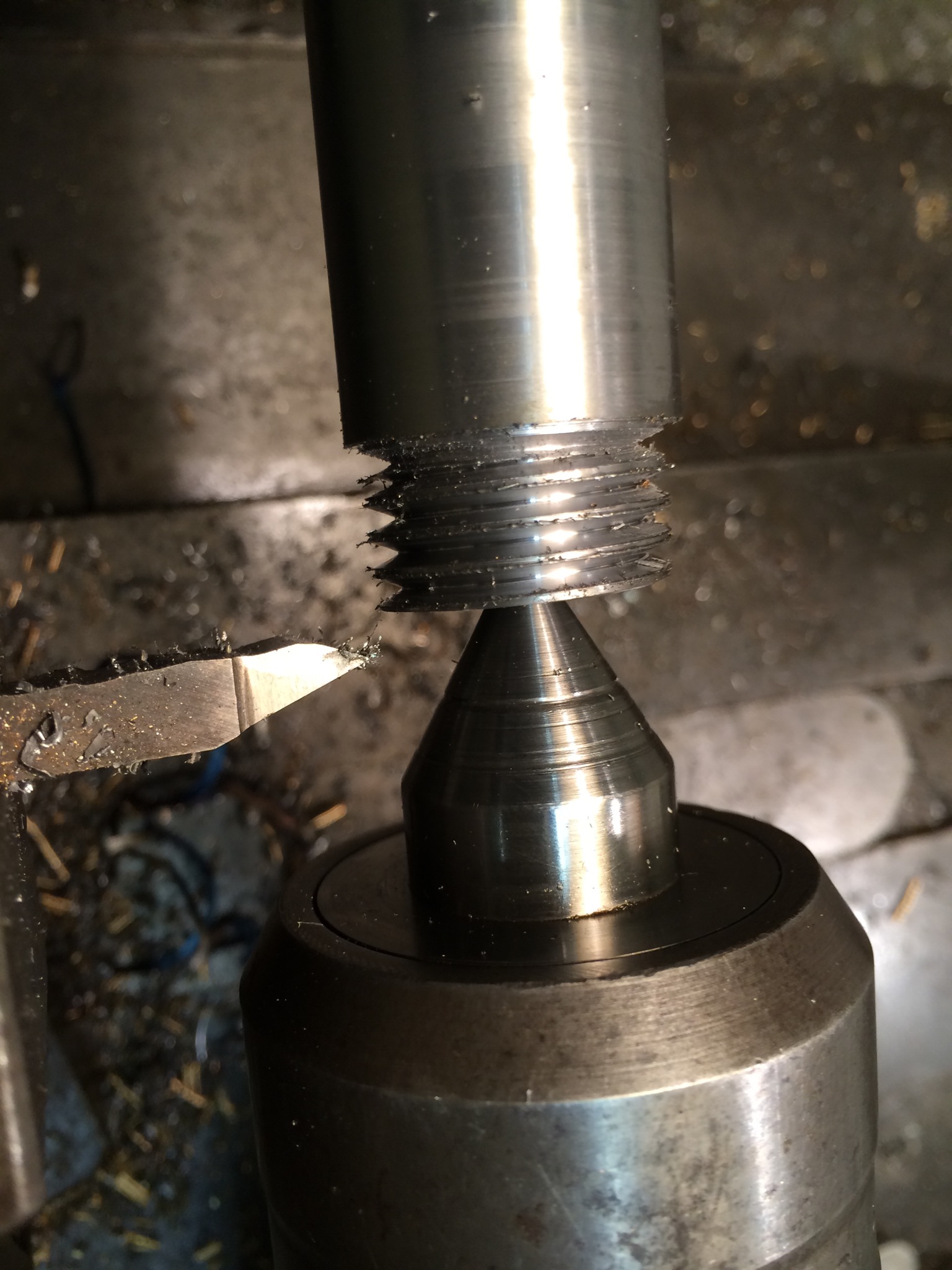
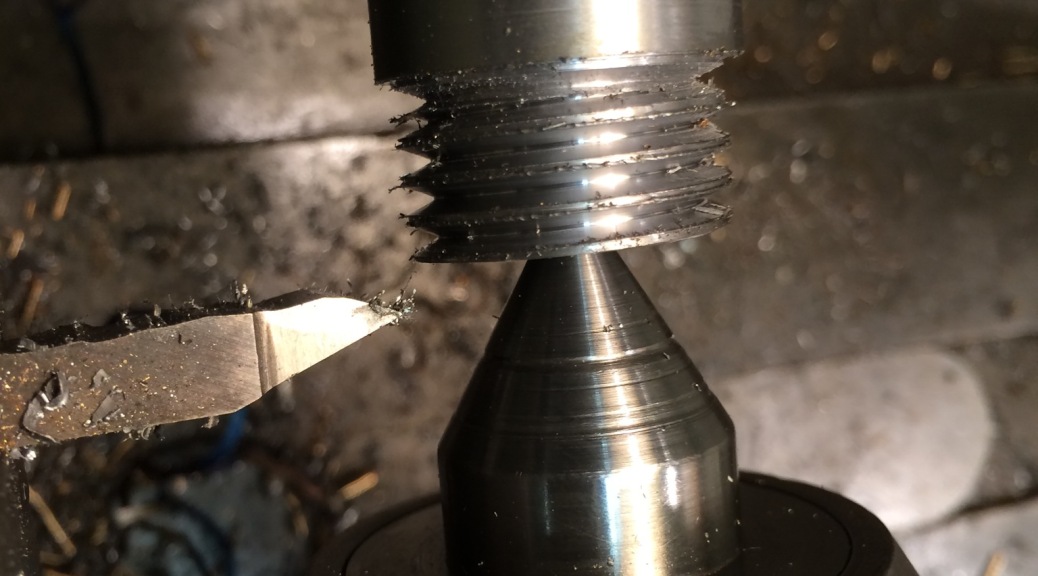
The next step was to turn the remainder of the hob blank down to diameter and cut an identical thread. The turning part went without a hitch (once I had ground myself a decent HSS bit) but unfortunately I got too ambitious when feeding in the threading tool and ended up snapping the tip off the tool. Perhaps the bright blue colour of some of the swarf should have given me a clue.
To be continued, once I’ve reground the threading tool…