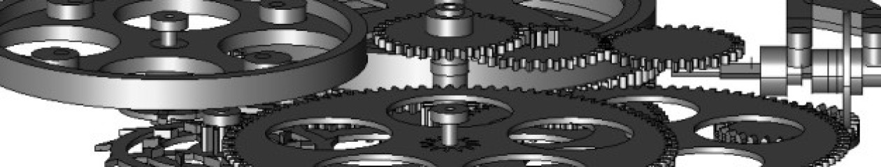
The basic principle of wheel cutting does not seem complicated. Starting with a blank the correct full diameter for the number of teeth, a cutter is used to shape the gap between two teeth. The workpiece spindle is then rotated by the angle corresponding to the tooth width and the cycle repeated until the desired number of teeth have been formed.
The workpiece spindle rotation is typically controlled either using direct indexing, where a detent acts on a disk with the same number of teeth as the wheel being cut (or a multiple of it), or using a dividing head, where there is a reduction drive between the detent and the spindle. Direct indexing reduces the scope for mistakes but is less flexible, needing different index disks for wheels with different numbers of teeth.
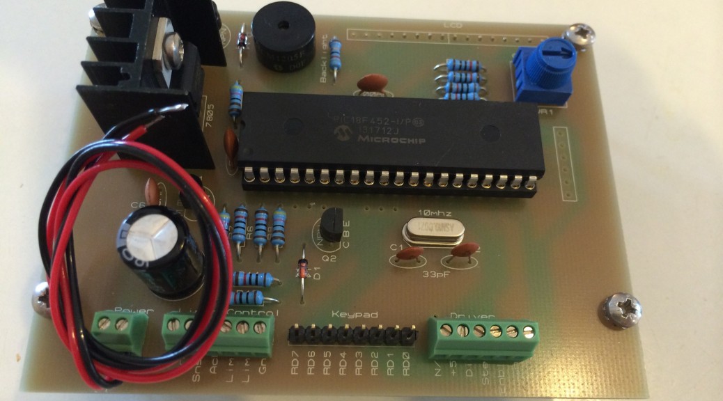
A good solution appears to be to use electronics and a stepper motor to control the rotation of the workpiece spindle with the press of a button. The engineer in me tells me to programme my own micro controller (such as a PIC) to achieve this as I did with the bike light controller. The realist in me tells me that the aim of this project is to make a watch, not to make parts, so let’s look for an off-the-shelf solution.
The first solution I came across was DivisionMaster. This looked to offer the functionality I was after but the price put me off (this is only a hobby after all). A while after I found DivisionMaster I found various posts on the CNCZone forum talking about another PIC-based solution by Steve Ward. This is the one I now have and it looks to be very well made. One plan is to connect a microswitch to the external trigger line such that when I withdraw the mill table after making one cut, the switch is closed and the indexer moves on automatically, ready for the next cut.
What remains to be worked out is how best to attach the stepper motor that this drives to to workpiece spindle. Some gearing down of the stepper rotation is needed, since most steppers only have 200 steps per revolution, which won’t be enough for cutting wheels with, for example, 72 teeth. As always, there are at least three different options for the gearing: a planetary gearbox, a worm drive, or a harmonic drive. The worm drive would probably have less backlash than the planetary gearbox, but the winner in terms of minimal (claimed zero) backlash is the harmonic drive.
After starting to make a worm drive myself, I resorted to buying a precision worm drive and fitting it to the indexing spindle of the Aciera F1.
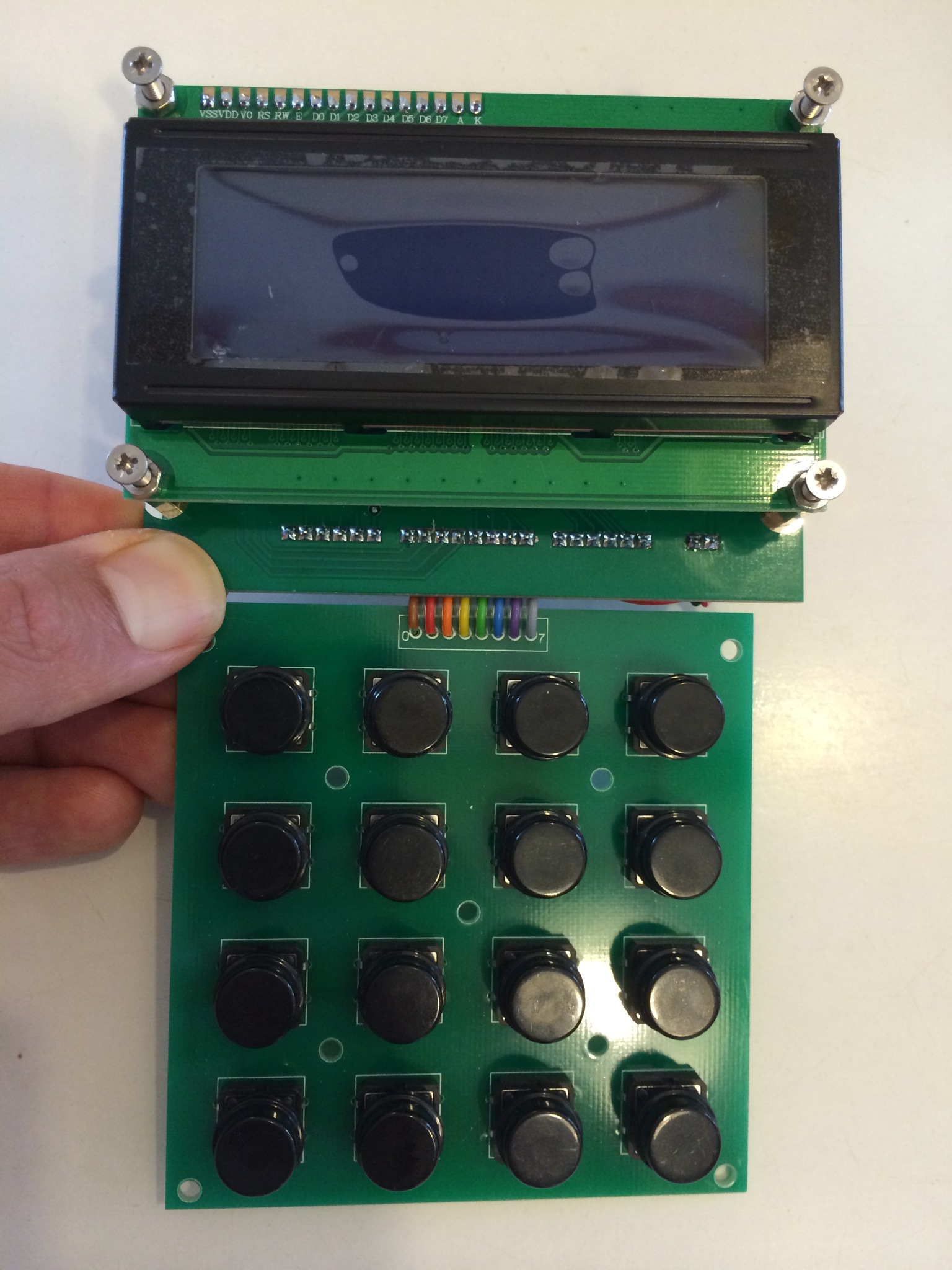
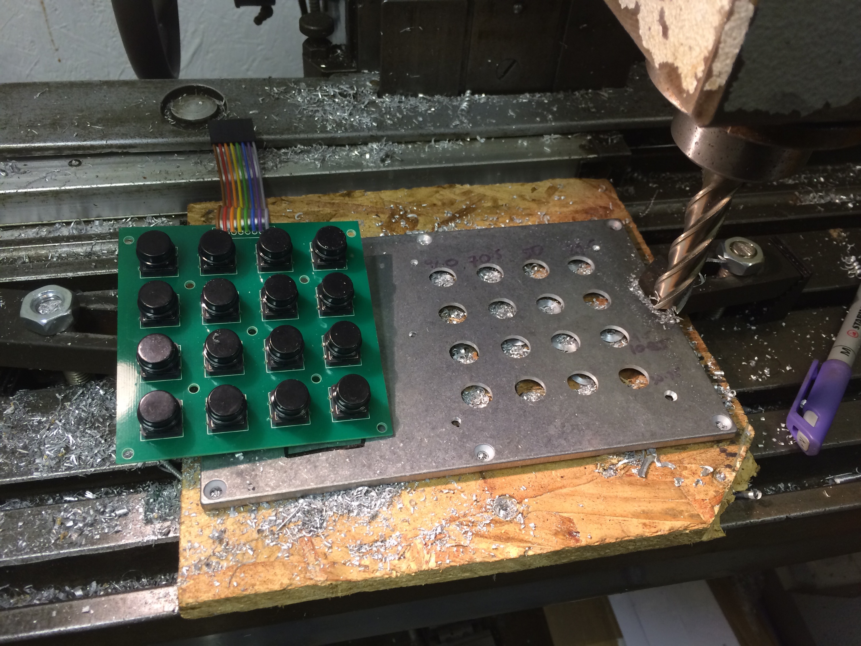
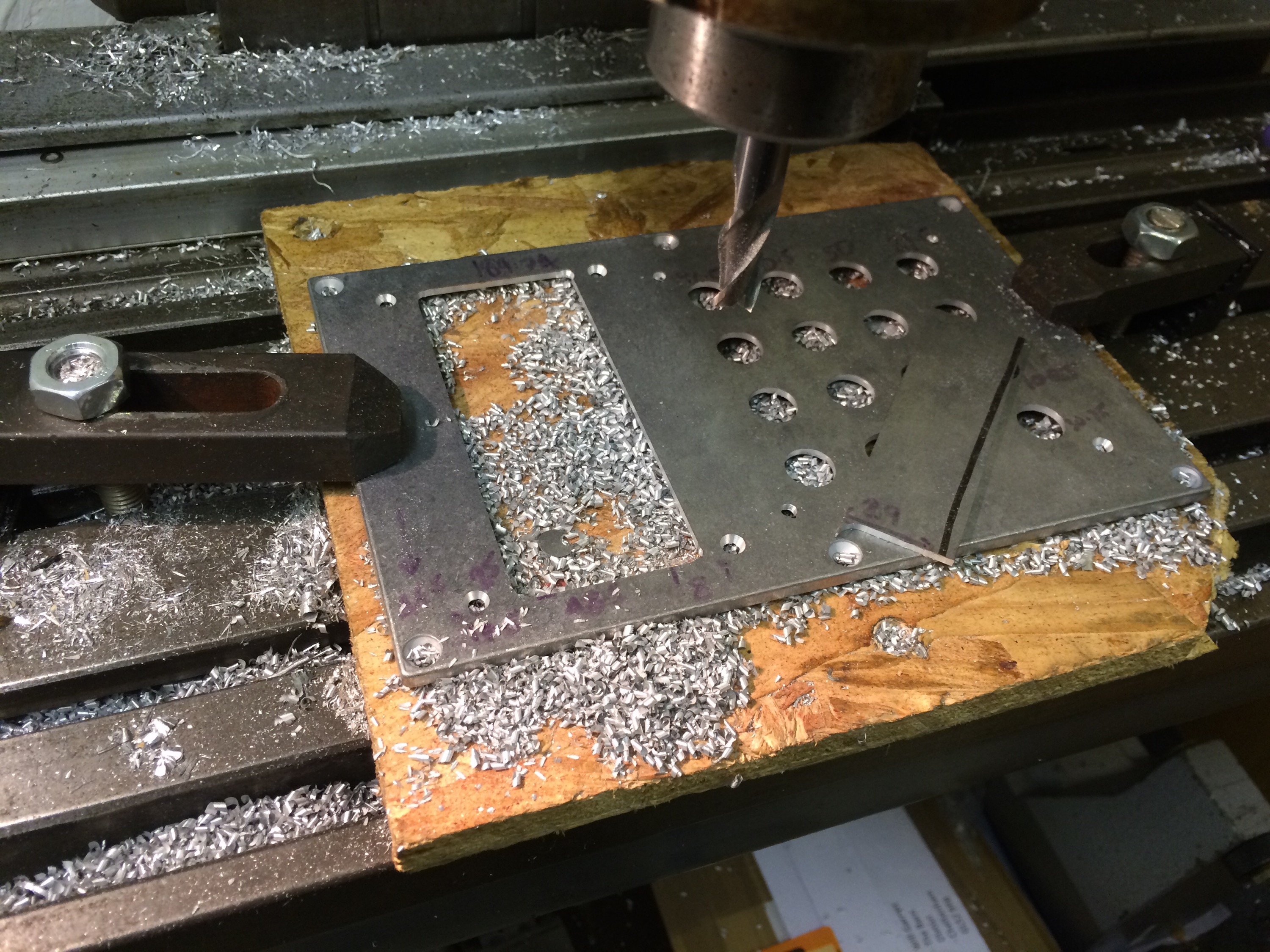
The Ward controller was boxed up, together with a stepper motor driver. The holes for the keypad and display were drilled on the Aciera F3:
I have bought sockets for the power, stepper and external control leads but so far not used them, instead just feeding the power and stepper cables through holes in the box to cut down on the number of potential points of failure. I have yet to do anything with the external control that the Ward controller offers, I’ll add it once I find a use for it. As can be seen in the photo below, I have yet to add any keypad labels but it works for what I want to do so far.
